
Methods and devices for static or dynamic spine stabilization

Inactive Publication Date: 2007-12-27
KIC VENTURES LLC
View PDF28 Cites 40 Cited by
  • Summary
  • Abstract
  • Description
  • Claims
  • Application Information

AI Technical Summary

Benefits of technology

[0015]Among the advantages of this invention may be one or more of the following. The improved spine fixation system allows motion between the segments to be fused away from the fixation points. The dynamic fixation system provides bidirectional motion between the fused segments during compression (neck flexion) and distraction (extension and lying supine). The plates are allowed to pivot and / or slide longitudinally and / or horizontally relative to each other at a point between the fused segments. The plates can be placed at an angle relative to each other. This new dynamic plating system offers superior fusion rates since it allows continuous graft loading and natural graft subsidence while acting as a block to anterior graft displacement.

Problems solved by technology

However, disorders of the spine occur when one or more of these spine structures are abnormal.
It is thought that plates also increased the rate of fusion and decreased the incidence of graft complications such as graft extrusions and subsidence.
One of the disadvantages of current anterior cervical plates includes the lack of graft subsidence and continuous graft loading which is believed to be advantageous for fusion.
It is also difficult to place the plate in a straight line longitudinally between adjacent vertebras and plates are therefore often inadvertently placed at an angle.
These technical difficulties often lead to a higher rate of complications including failure of the graft to fuse (pseudoarthrosis) and failure of the moveable (dynamic) mechanism to work, or failure of the plate-screw interface due to abnormal angular and rotational forces.
However, the limitations of dynamic plating systems include, potential failure of the moveable mechanism to work if the plates are placed at an angle between the vertebral bodies to be fused, lack of bidirectional movements during compression (neck flexion) and distraction (extension and lying supine), and lack of variable compression rates during sudden neck movements.

Method used


Image

  • Methods and devices for static or dynamic spine stabilization
  • Methods and devices for static or dynamic spine stabilization
  • Methods and devices for static or dynamic spine stabilization

Examples


Embodiment Construction

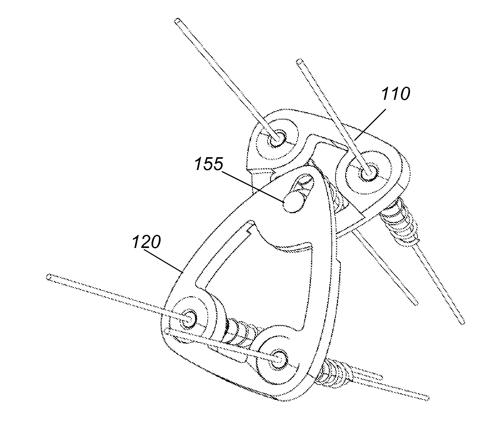
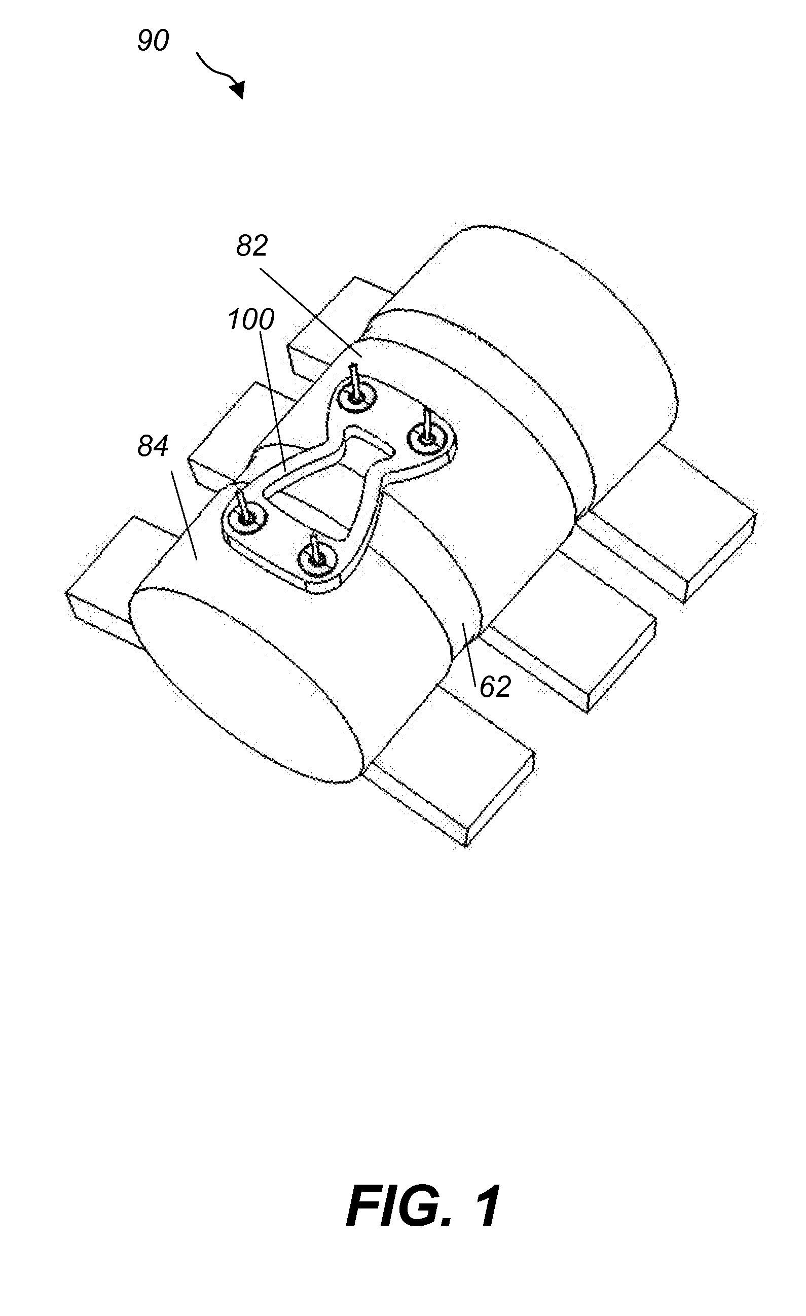
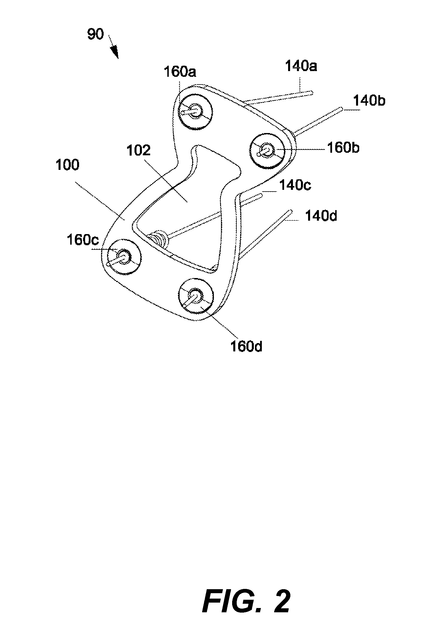
[0041]Referring to FIG. 1, FIG. 2 and FIG. 3, an anterior one-level fixed cervical fusion system 90 includes a top loading, one-level fixed cervical plate 100 that connects two adjacent vertebras 82 and 84. The fixed cervical plate 100 is attached to the vertebras 82 and 84 via four screws 130a, 130b and 130c, 130d, respectively. The fixed cervical plate 100 has an hourglass shape and an hourglass shaped aperture 102 centered in the middle of the plate 100. Aperture 102 provides visibility and access to the vertebras 82, 84 and disc 62 below the plate 100. Plate 100 also has four holes 162a, 162b, 162c and 162d located in the four corners of the plate. Holes 162a, 162b, 62c, 162d are dimensioned to receive the four screws 130a, 130b, 130c, 130d, respectively.

[0042]Referring to FIG. 4A, 4B, 4C, 4D, the process for attaching the plate 100 to the adjacent vertebras 82, 84 includes the following steps. First, four k-wires 140a, 140b and 140c, 140d are inserted into the vertebras 82 and ...


PUM


Abstract

Methods and devices for static or dynamic spine stabilization include an anterior plating system that allows longitudinal and pivoting motion of the plates and of the stabilized vertebras. In one embodiment a spine fixation assembly for connecting a first vertebra to a second vertebra includes a first plate configured to be attached to one or more locations of the first vertebra and a second plate configured to be attached to one or more locations of the second vertebra. The first plate is pivotally connected to the second plate and may also allow longitudinal and / or horizontal motion of the plates relative to each other.

Description

CROSS REFERENCE TO RELATED CO-PENDING APPLICATIONS[0001]This application claims the benefit of U.S. provisional application Ser. No. 60 / 811,593 filed Jun. 7, 2006 and entitled “METHODS AND DEVICES FOR STATIC OR DYNAMIC SPINE STABILIZATION”, the contents of which are expressly incorporated herein by reference.FIELD OF THE INVENTION[0002]The present invention relates to methods and devices for static or dynamic spine stabilization, and more particularly to methods and devices including an anterior plating system that allows longitudinal and pivoting motion of the plates and therefore of the stabilized vertebras.BACKGROUND OF THE INVENTION[0003]The human spine consists of individual vertebras (segments) that are connected to each other. Under normal circumstances the structures that make up the spine function to protect the neural structures and to allow us to stand erect, bear axial loads, and be flexible for bending and rotation. However, disorders of the spine occur when one or more...

Claims


Application Information

Patent Timeline
IPC IPC(8): A61F2/30
CPCA61B17/7058A61B17/7059A61B17/8897A61B17/864A61B17/8004
Inventor CHIN, KINGSLEY R.CHANG, CHRISTOPHER A.
Owner KIC VENTURES LLC
Learn More