System for Managing Ventilator Operation

a ventilator and operation technology, applied in the field of processing devices and display systems, can solve the problems of space, power, existing processing and display systems, described above, and the limitations of monitor processing devices and display to be able to view and control parameters

Active Publication Date: 2008-01-03
DRAGERWERK AG
View PDF37 Cites 191 Cited by
  • Summary
  • Abstract
  • Description
  • Claims
  • Application Information

AI Technical Summary

Problems solved by technology

In an operating room, where many such modules may be in use concurrently, this requires space, and power.
The existing processing and display systems, described above. used in patient monitoring and treatment have numerous limitations.
Further, in existing systems, medical device processing devices and displays are typically able to view and control parameters and functions of other like devices, that is, a monitor processing device and display is limited to be able to view and control parameters and functions of another monitor processing device and display.
These devices require multiple individual electrical connections and fail to provide inter-device communication and central parameter processing capability.
Because the different patient monitoring and / or treatment modules are from different sources and include different user interfaces, there is a significant risk of a mistake being made in the settings of one device based on the readings from another.
Therapeutic limitations, both in recruitment maneuvers and in maneuvers to determine the ideal ventilation settings, are typically the high pressures exerted over a long period of time on the chest cavity which reduce the venous return flow to the right heart and thus the cardiac output and the arterial pressure.
However, the additional volume of circulating blood may result in the negative effect of increasing the intrathoracal pressure in the patient's chest cavity.
Furthermore, if the pressure is suddenly and drastically reduced, the blood volume suddenly flowing back out of the capacity vessels (i.e., veins) into the right heart may overstrain the heart, particularly in patients with a coronary heart condition.
If there is an insufficiency of the left heart, excessive volume input can lead to lung edema.

Method used


Image

  • System for Managing Ventilator Operation
  • System for Managing Ventilator Operation
  • System for Managing Ventilator Operation

Examples


Embodiment Construction

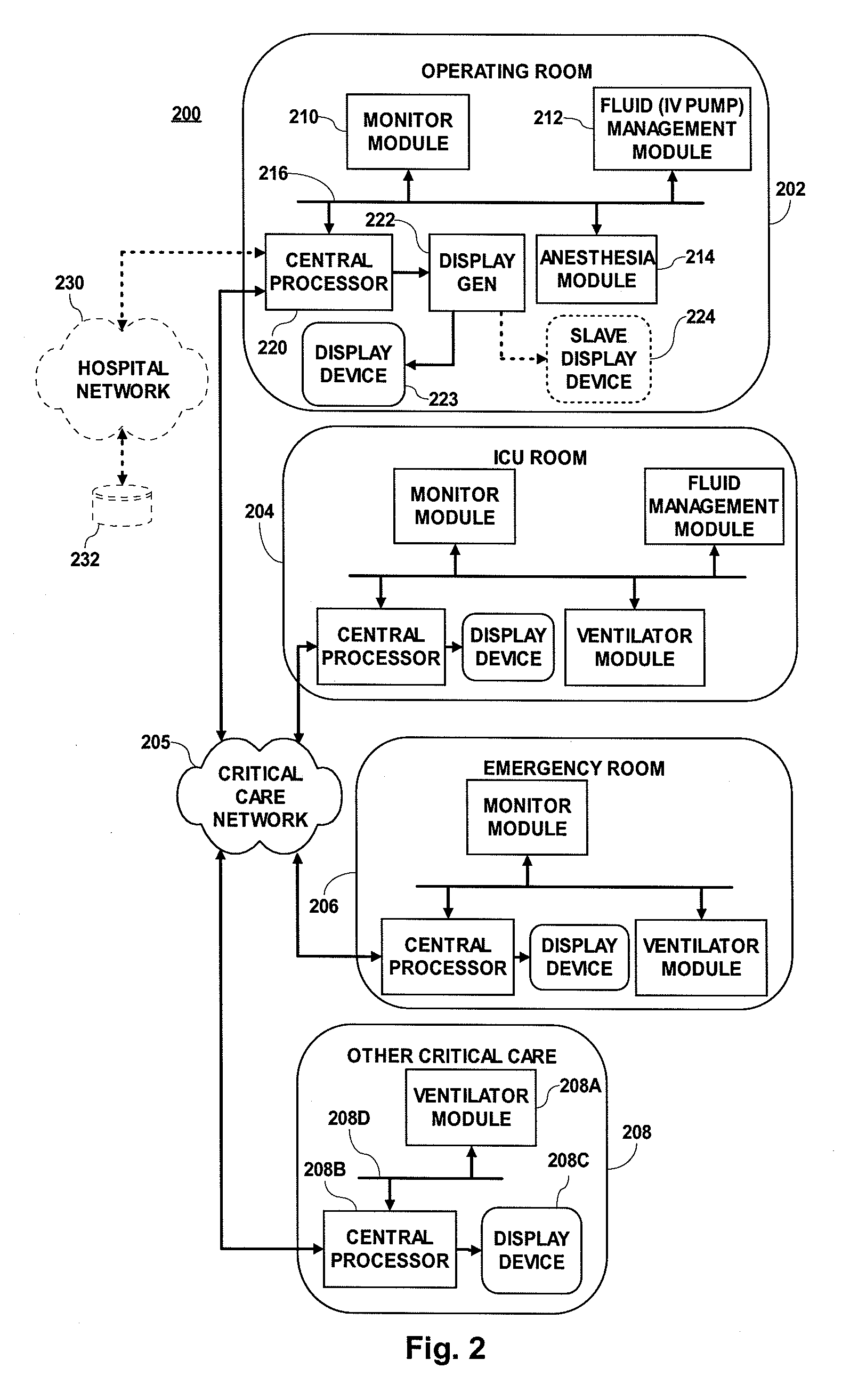
[0025]FIG. 2 is a block diagram of a hospital system 200 for monitoring and providing treatment to patients. In FIG. 2, the same four rooms are illustrated as are illustrated in FIG. 1, and those rooms contain the same medical equipment. The operating room 202 includes a patient monitoring module 210 for acquiring and processing signals derived from sensors (not shown) suitable for attachment to a patient. The operating room 202 also includes patient treatment modules: a fluid infusion (IV pump) control and management module 212 and an anesthesia module 214. These modules (210, 212 and 214) are coupled to a central processor 220 via a patient area network (PAN) 216. The central processor 220 is coupled to a display generator 222 which is coupled to a display device 223. The display generator 222 is also optionally coupled to a slave display device 224, as illustrated in phantom. The ICU room 204 includes a monitor module, a fluid management patient treatment module and a ventilator ...


PUM


Abstract

A method for managing patient ventilator operation includes receiving data representing one or more hemodynamic parameters. In response to the received data representing the one or more hemodynamic parameters, one or more commands are provided for adaptively altering ventilator operation.

Description

CROSS REFERENCE TO RELATED APPLICATIONS [0001] This application is a continuation-in-part of U.S. patent application Ser. No. 10 / 976,025 filed Oct. 28, 2004.FIELD OF THE INVENTION [0002] The present invention relates to a processing device and display system, and in particular to a method and a system for incorporating hemodynamic and electrophysiological information into ventilation maneuvers. BACKGROUND OF THE INVENTION [0003] Hospitals routinely monitor physiological parameters of patients from first entry until final release. Originally, this was performed by one or more patient monitoring devices, such as a heart rate monitor, an EKG monitor, an SpO2 monitor, and so forth. These physiological parameters were separately detected by separate pieces of equipment, possibly manufactured by respectively different manufacturers. The monitoring equipment included the connections to the patient necessary to measure the physiological parameter and a display device of the type necessary t...

Claims


Application Information

Patent Timeline
Patent Type & Authority Applications(United States)
IPC IPC(8): A61M16/00A61B5/00A61B10/00
CPCA61B5/412A61B5/002A61M16/0066A61M16/16A61M2205/3561A61M2205/3584A61M2205/3592A61M2205/502A61M2205/8206A61M2230/04A61M2230/06A61M2230/10A61M2230/205A61M2230/42G06F19/3418G06F19/3481A61M16/0051A61M2230/005A61M16/024G16H20/17G16H40/63G16H50/20G16H30/20A61M2230/60A61M16/1005A61M16/0003A61M16/10A61M2205/33A61M2205/3303A61M2205/3327A61M2230/30
Inventor ELAZ, JOSEPHSCHOLZ, WOLFGANGCAVALLARO, SAMUELBUTTERBRODT, JAYRALFS, FRANK
Owner DRAGERWERK AG
Why Eureka
Try Eureka