
Oropharyngeal Airway

a technology of oropharyngeal airway and airway, which is applied in the direction of respiratory apparatus, medical devices, medical devices, etc., can solve the problems of irritation of the trachea, inconvenient administration of anesthesia via face mask technique, and difficulty in establishing and maintaining an airway of patients

Inactive Publication Date: 2008-01-03
GANESH ARJUNAN +2
View PDF21 Cites 28 Cited by
  • Summary
  • Abstract
  • Description
  • Claims
  • Application Information

AI Technical Summary

Benefits of technology

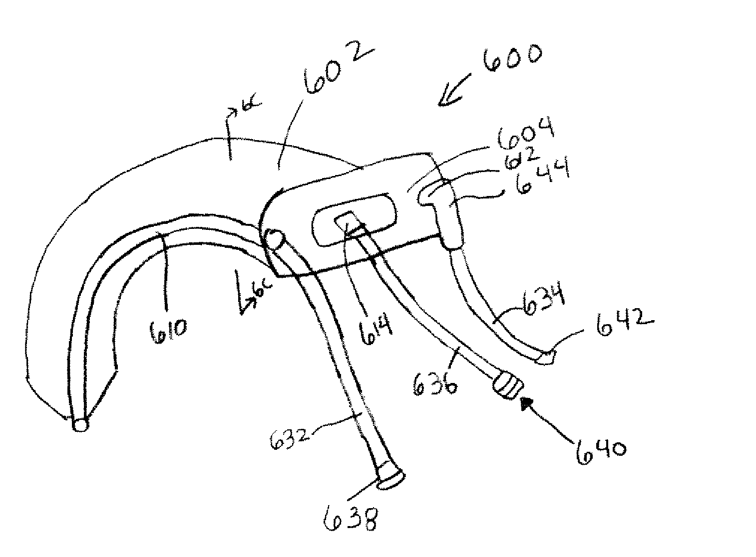
"The invention is an oropharyngeal device that can be inserted into a patient's mouth to establish and maintain an airway. The device has a body with a distal end that can be inserted into the mouth and a proximal end that is outside and adjacent to the patient's mouth. The device has at least one channel that forms an airway within the body of the device. The device can be connected to an inhalant gas source, a suctioning device, and a gas sampling device to facilitate the delivery of inhalant gas and the monitoring of end-tidal carbon dioxide. The device can be used to maintain an airway in patients who are unable to breathe on their own."

Problems solved by technology

This is inconvenient during certain medical procedures that require access to the face because the face mask technique may obstruct access to the face.
If a mask is used to administer anesthesia during such procedures, access the patient's face may be hindered.
Further, in such circumstances, anesthesiologists often use awkward hand positioning to allow access to the face which then requires repeated manipulation of the mask to ensure a patent airway.
The administration of anesthesia via a face mask technique is also inconvenient when the anesthesiologist must be distant from the patient such as during radiation therapy, CT or CAT scans, and during MRIs.
Although the anesthesiologist may repeatedly instrument the trachea in such circumstances, the stimulation may result in irritation of the trachea especially when treatment is necessary on an on-going basis.
Repeated instrumentation during this on-going treatment will irritate the patient's trachea and may result in other adverse consequences such as a sore throat and loss of appetite due to the irritated trachea and hypopharynx.
Each of these solutions has its respective drawbacks especially during procedures such as radiation treatment where deep anesthetization is not necessary, where the patient breathes by himself and where treatment is on an on-going basis.
Thus, endotracheal intubation is not desirable for circumstances that do not require deep anesthetization.
Endotracheal intubation also subjects the patient to laryngoscopy for inserting the endotracheal tube and to tracheal irritation which makes it undesirable for circumstances requiring repeated instrumentation.
Intravenous techniques may obviate the use of inhalational agents, but still necessitate maintenance of a patent airway.
However, the LMA must be connected to a conventional anesthesia circuit, does not provide a mechanism for suctioning secretions, and requires technical facility for its insertion that may require adjunctive equipment for its application.
This stimulation is undesirable in circumstances requiring repeated instrumentation.
However, the COPA must be connected to a conventional anesthesia circuit or to an adapter to connect the COPA to an oxygen source and may cause the patient discomfort due to the inflated cuff.
Further, the COPA does not include a suctioning mechanism which may result in a medical procedure being interrupted in order for an anesthesiologist to suction the patient when secretions are building up.
Further, there is a need for such a device that is minimally stimulating to allow for repeated use during on-going treatments, that does not block access to the face of a patient, and that allows an anesthesiologist to be distant from the patient.

Method used


Image

  • Oropharyngeal Airway
  • Oropharyngeal Airway
  • Oropharyngeal Airway

Examples


Embodiment Construction

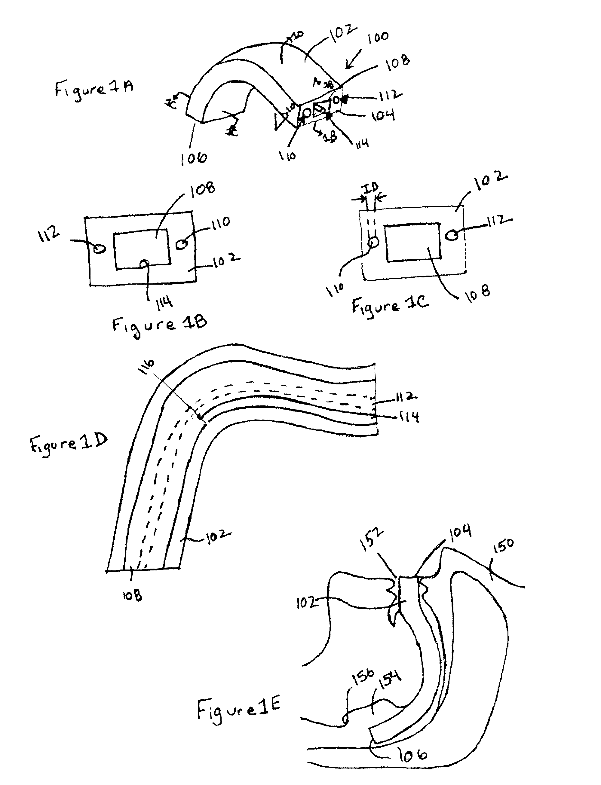
[0034] Referring to the drawings in which like reference numerals indicate like elements, there is shown in FIGS. 1A-E an oropharyngeal device 100 according to an exemplary embodiment of the present invention. The device 100 includes a body 102 having a proximal end 104 and a distal end 106.

[0035] A channel 108 forms an airway through the body 102 that extends through the body 102 from its proximal end 104 to its distal end 106. As illustrated in FIG. 1E, the body 102 is sized such that when the distal end 106 of the body 102 is inserted into the mouth 152 of a patient 150 until the proximal end 104 is disposed outside and adjacent to the patient's mouth 152, the distal end 106 of the body 102 is disposed within the pharynx 154 above the epiglottis 156. The body 102 may be formed of a rigid material to serve as a bite block to prevent the patient from biting any conduits inserted through the channel.

[0036] The airway channel may be completely enclosed within the body of the oropha...


PUM


Abstract

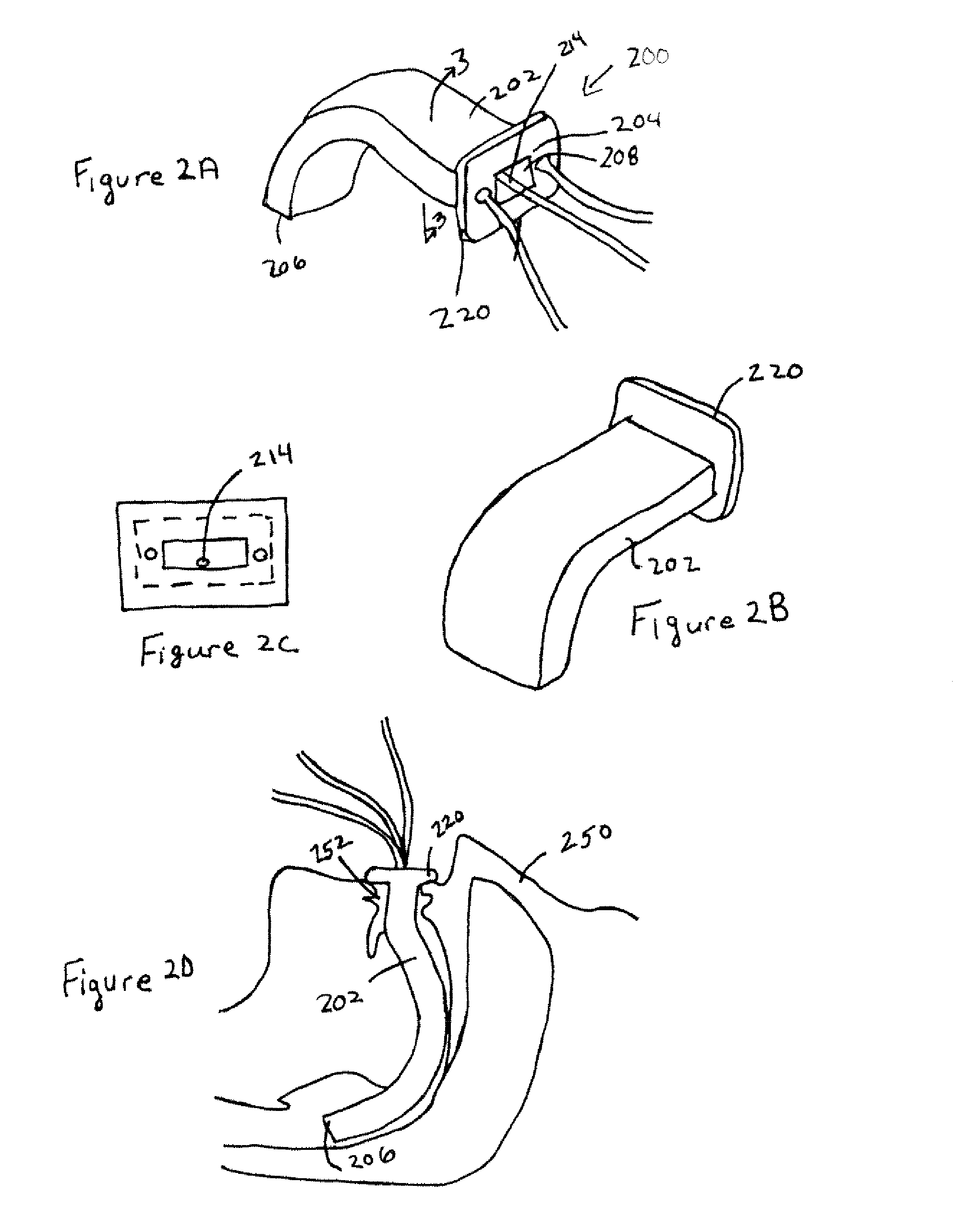
An oropharyngeal device for insertion into the mouth of a patient. The device includes a body having a distal end and a proximal end with a flange formed at the proximal end. The distal end of the body is inserted into the mouth of the patient until the flange at the proximal end is disposed outside and adjacent to the patient's mouth. The flange keeps the proximal device from entering the mouth. The body is sized such that the distal end of the body is disposed within the pharynx above the epiglottis. The device includes a channel through the body that forms an airway between its proximal and distal ends. The device also includes at least three separate conduits integrated into the body for administering oxygen, suctioning, and for assessing ventilation through end-tidal carbon dioxide monitoring. The conduits for oxygenation and suctioning extend through the body between its proximal and distal ends. The conduit for end-tidal carbon dioxide monitoring extends along and is attached to a side wall of the channel and terminates within the channel.

Description

CROSS-REFERENCE TO RELATED APPLICATIONS [0001] The present invention is related to and claims priority from co-pending U.S. patent application Ser. No. 10 / 666,290 filed Sep. 19, 2003 and from U.S. Provisional Patent Application Ser. No. 60 / 413,174, filed Sep. 14, 2002, both being incorporated by reference herein in their entirety.FIELD OF THE INVENTION [0002] The invention relates to establishing and maintaining an airway and, in particular, to an oropharyngeal device for establishing and maintaining an airway. BACKGROUND OF THE INVENTION [0003] The administration of anesthesia via a face mask technique usually requires continuous hands-on management. This is inconvenient during certain medical procedures that require access to the face because the face mask technique may obstruct access to the face. [0004] For example, access to the face may be necessary for ophthalmologic examination, radiation therapy, MRIs (magnetic resonance imaging), and CT (computed tomography) or CAT (comput...

Claims


Application Information

Patent Timeline
Patent Type & Authority Applications(United States)
IPC IPC(8): A61M16/00A61M16/04
CPCA61M16/04A61M16/0463A61M16/0493A61M2230/432A61M2210/0656A61M16/0495A61M16/085
Inventor GANESH, ARJUNANARMSTEAD, VALERIE E.WILLIAMS, MICHAEL J.
Owner GANESH ARJUNAN
Learn More