Thermal printer and method of forming image

a printer and thermal technology, applied in the field of thermal printers, can solve the problems of difficult to obtain visually vivid matte effects, limit the degree of unevenness,

Inactive Publication Date: 2008-01-03
SONY CORP
View PDF5 Cites 2 Cited by
  • Summary
  • Abstract
  • Description
  • Claims
  • Application Information

AI Technical Summary

Benefits of technology

[0019] Therefore, in the formed convexo-concave pattern, convex and concave portions are sufficiently different. Hence, visually vivid matte effects can be obtained.

Problems solved by technology

Consequently, there is a limitation in the degree of the unevenness.
There is the problem that it is difficult to obtain visually vivid matte effects.

Method used


Image

  • Thermal printer and method of forming image
  • Thermal printer and method of forming image
  • Thermal printer and method of forming image

Examples


Embodiment Construction

[0029] Embodiment of the present invention are hereinafter described with reference to the drawings.

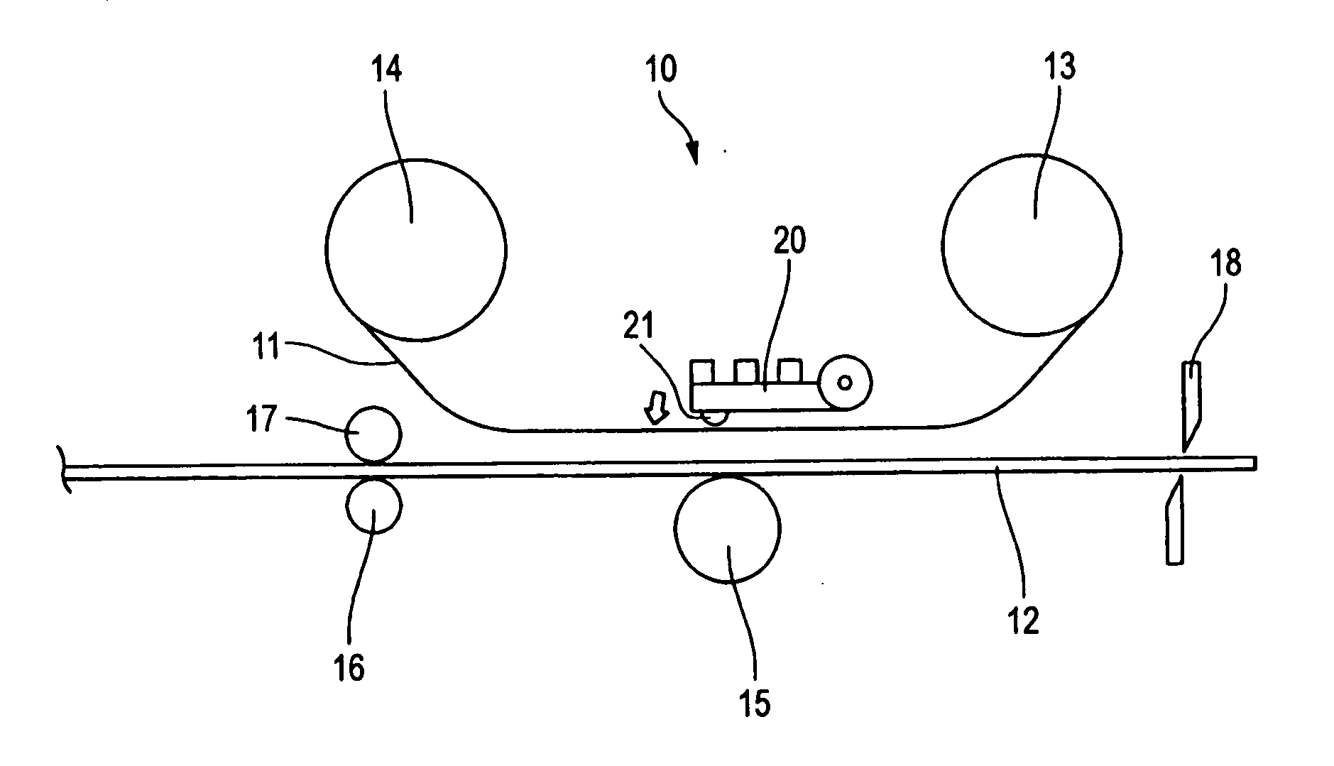
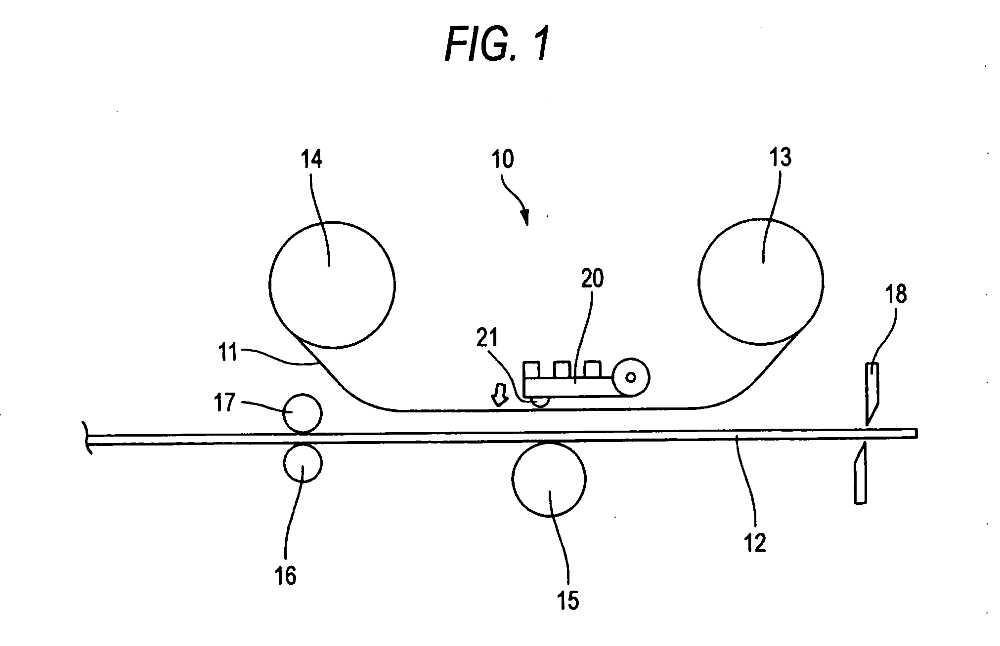
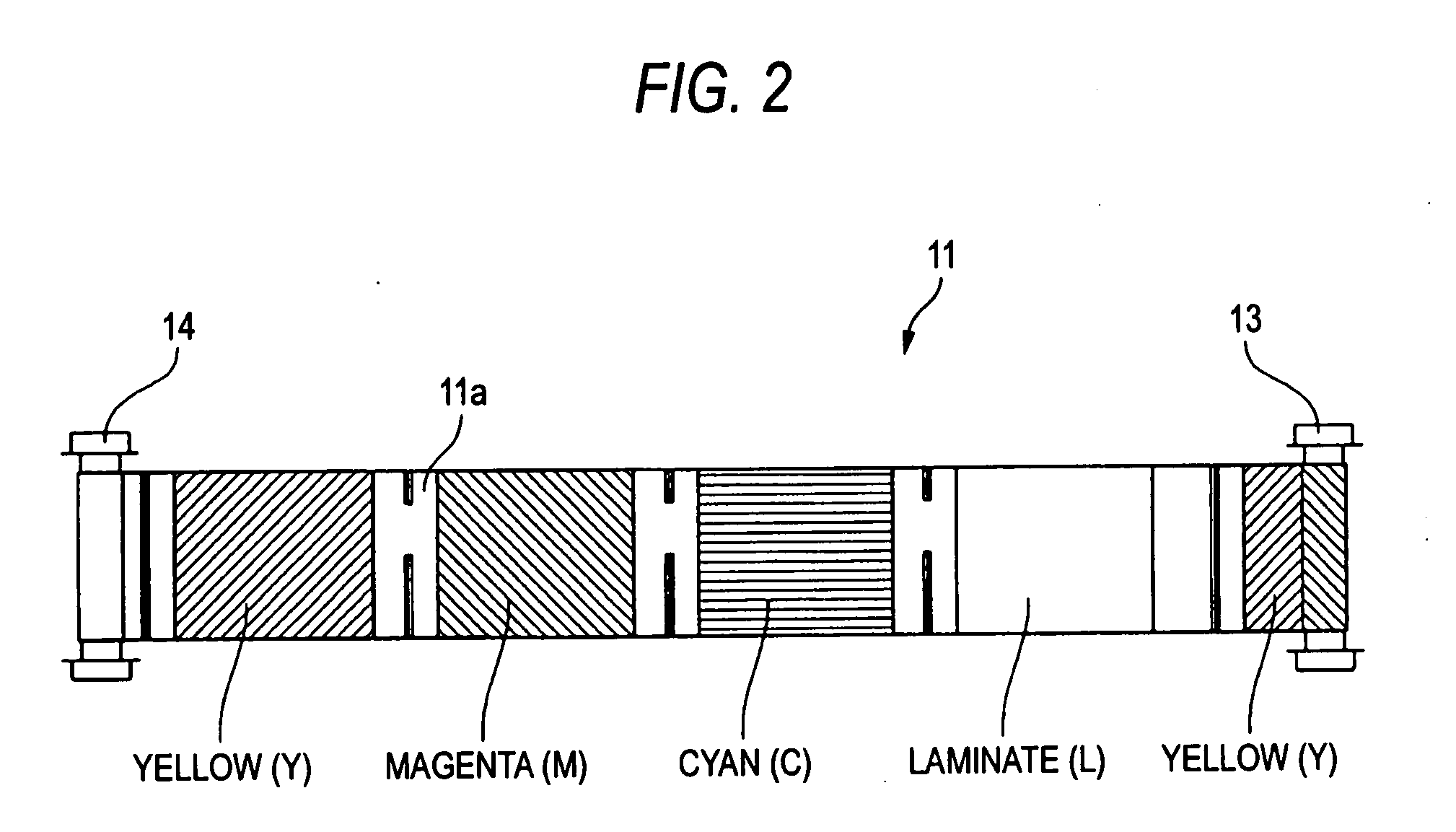
[0030]FIG. 1 is a side elevation showing a thermal printer 10 according to one embodiment of the present embodiment. The thermal printer 10 corresponds to color printing. An ink ribbon 11 to which three color inks (yellow (Y), magenta (M), and cyan (C)) are applied together with a transparent laminate ink (L) is mounted on the printer.

[0031] The thermal printer 10 is of the dye sublimation type and sublimates the sublimation inks applied on the ink ribbon 11 by making use of thermal energy produced when plural heat-generating resistors 21 (corresponding to heat-generating elements in the present invention) arrayed on a thermal head 20 are electrically energized. The inks are transferred to roll paper 12 (corresponding to paper in the present invention) to perform printing.

[0032] The thermal head 20 can be moved toward and away from a platen roller 15 (corresponding to the platen in...


PUM


Abstract

A thermal printer is disclosed. The thermal printer includes a thermal head on which plural heat-generating elements are arrayed; and a platen mounted opposite to the thermal head. The thermal printer uses an ink ribbon and paper held between the thermal head and the platen, and the thermal printer performs printing by causing the heat-generating elements to generate heat such that inks of the ink ribbon are transferred to the paper. The ink ribbon has a base film on which color inks and a transparent laminate ink are successively and repetitively arranged, and a pressure force acting between the thermal head and the platen is made different between when the color inks are transferred and when the laminate ink is transferred.

Description

CROSS REFERENCES TO RELATED APPLICATIONS [0001] The present invention contains subject matter related to Japanese Patent Application JP2006-183909 filed in the Japanese Patent Office on Jul. 3, 2006, the entire contents of which being incorporated herein by reference. BACKGROUND OF THE INVENTION [0002] 1. Field of the Invention [0003] The present invention relates to a thermal printer for printing an image by placing an ink ribbon and paper between a thermal head and a platen and transferring the inks of the ink ribbon onto the paper. The invention also relates to a method of forming an image using the thermal printer. More particularly, the invention relates to a technique for producing vivid visual effects by forming sufficient convexes and concaves on the surface of the paper. [0004] 2. Description of the Related Art [0005] A thermal printer having a thermal head including arrays of plural heat-generating elements (such as heat-generating resistors) and a platen (e.g., a platen r...

Claims


Application Information

Patent Timeline
Patent Type & Authority Applications(United States)
IPC IPC(8): B41J2/325
CPCB41J2/325
Inventor KATO, HIROAKIHIRUMI, YASUSHI
Owner SONY CORP
Why Eureka
Try Eureka