Hip prosthesis provided with a shaft inserted into the femur

a technology of femur and prosthesis, which is applied in the field of hip prosthesis provided with a shaft inserted into the femur, can solve the problems of limited force force on the cortical bone, danger of bone breaking, and limited danger of fact, and achieves sufficient roughness. , the effect of sufficient roughness

Active Publication Date: 2009-06-30
WALDEMAR LINK GMBH & CO
View PDF43 Cites 1 Cited by
  • Summary
  • Abstract
  • Description
  • Claims
  • Application Information

AI Technical Summary

Benefits of technology

[0009]To ensure that the abrasive effect of the roughness is sufficient in the area of the rear of the rib, the distance between adjac

Problems solved by technology

Based on previous experience, one has to expect that a wide wedge-shaped rib of this kind will deploy its wedging effect mainly outwardly toward the cortical bone and that, therefore, there will be a danger of the bone breaking.
This danger would in fact arise if the rear face of the rib were not rough.
First, the force g

Method used


Image

  • Hip prosthesis provided with a shaft inserted into the femur
  • Hip prosthesis provided with a shaft inserted into the femur

Examples


Embodiment Construction

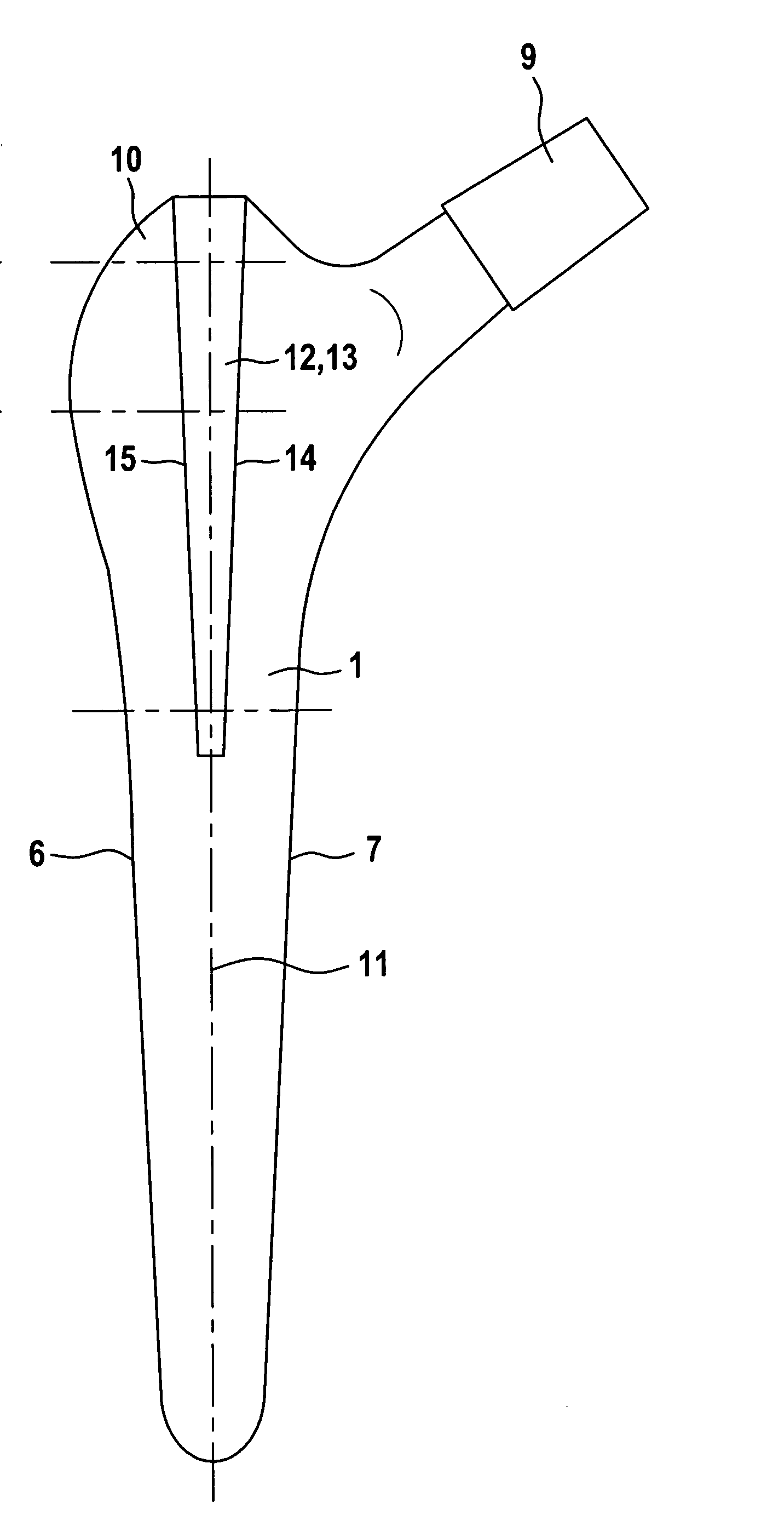
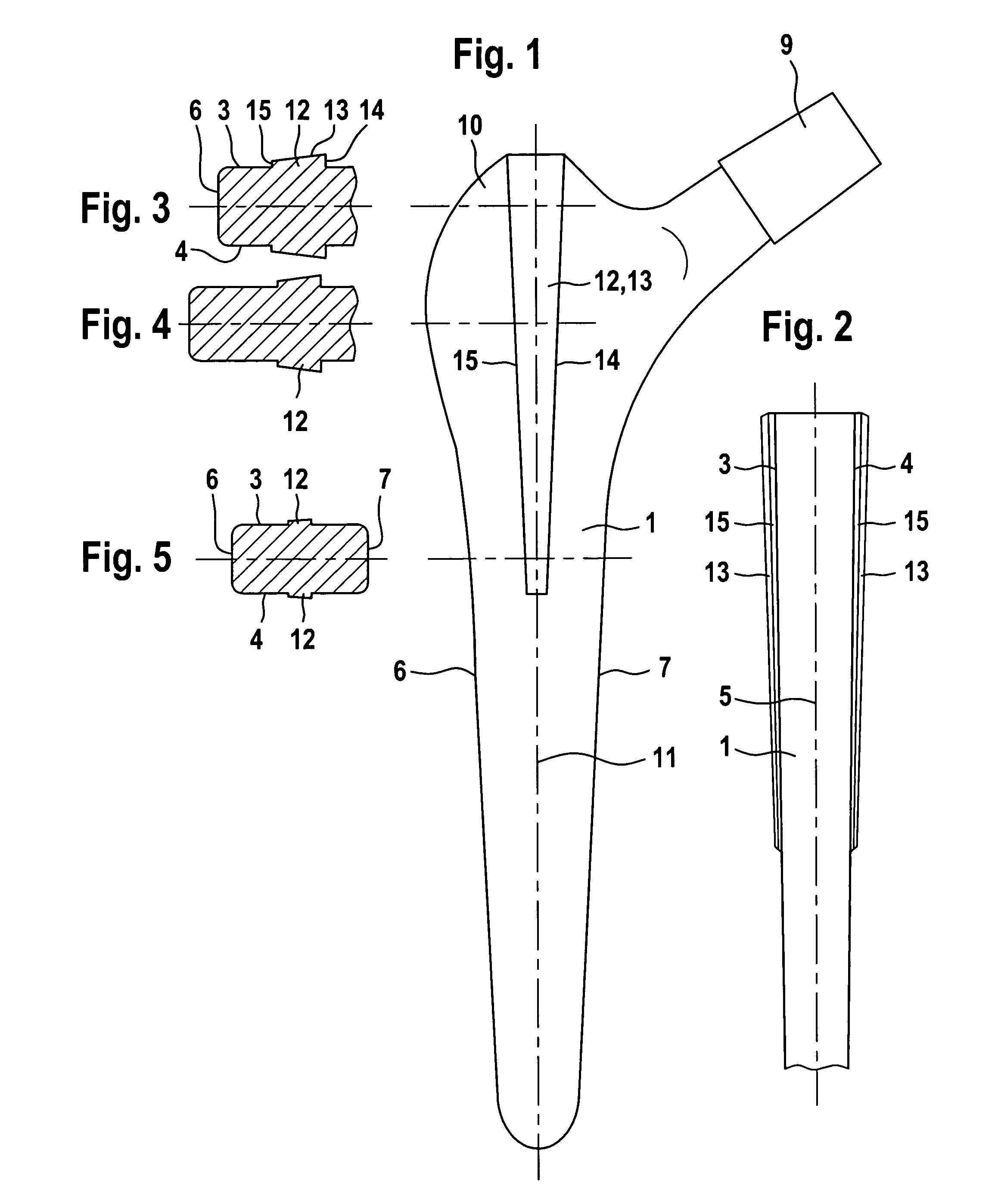
[0014]The prosthesis is a straight shaft prosthesis, that is to say the shaft has a continuously straight longitudinal axis and is implanted in a rectilinear direction into the femur. The shaft 1 comprises an in cross section substantially rectangular base body with parallel dorsal and ventral faces 3, 4 which taper in a wedge shape in the distal direction. They each enclose an angle of less than 2° with the lateral-medial midplane 5. The lateral and medial boundary faces 6, 7 of the base body of the shaft likewise taper in a wedge shape in the distal direction. The proximal end is adjoined by the prosthesis neck, having a cone 9 for attachment of a ball joint, and by a lateral wing 10 in the region of the greater trochanter.

[0015]A rasp (not shown) for forming the bone cavity intended to receive the prosthesis shaft has the same shape as the base body of the prosthesis shaft delimited by the faces 3, 4 and 6, 7, as is generally known, in order to give the prosthesis shaft a secure ...


PUM


Abstract

A hip prosthesis includes a shaft which can be inserted into a hole in the femur without using cement. The proximal section of the shaft includes a base body having a form that is complementary to the shape of the hole in the femur into which the shaft is to be inserted. The hole is made using a tool of a shape corresponding to the base body. The base body has a cuneus rib raised on its dorsal or ventral surface that has a width in its center that is at least three times its height. The rear surface of the cuneus rib has rough and abrasive properties.

Description

FIELD AND BACKGROUND OF THE INVENTION[0001]The part of a hip prosthesis assigned to the femur is equipped with a shaft inserted into a cavity which, after resection of the head and neck of the hip, is formed by a suitable tool in the spongy inner cross-sectional area of the femur. If the shaft is inserted without using cement, it is endeavored to make the shape of the cavity as far as possible complementary to the shape of the shaft, so that the prosthesis has a secure and firm fit after insertion of the shaft. The proximal portion of the shaft coming to lie in the metaphyseal region of the bone (approximately above the lesser trochanter) is designed in such a way that it can transmit not only vertical forces in the direction of the femur but also forces extending transverse thereto and, in particular, medially directed forces. To ensure that the surface areas of the proximal prosthesis shaft oriented in the ventral and dorsal directions also take part in transmission of forces to t...

Claims


Application Information

Patent Timeline
IPC IPC(8): A61F2/36A61B17/16A61F2/00A61F2/30
CPCA61F2/367A61B17/1659A61F2/30767A61F2/36A61F2/3676A61F2002/30153A61F2002/30324A61F2002/30332A61F2002/30879A61F2002/30906A61F2002/3625A61F2002/365A61F2002/3664A61F2220/0033A61F2230/0019A61F2250/0036A61F2002/30878
Inventor KELLER, ARNOLD
Owner WALDEMAR LINK GMBH & CO
Why Eureka
Try Eureka