
Lithium secondary battery

a secondary battery and lithium battery technology, applied in the direction of cell components, final product manufacturing, sustainable manufacturing/processing, etc., can solve the problems of low yield of integrated sintered plate batteries, inability to achieve capacity as expected, etc., and achieve the effect of producing with high yield and larger roughness

Pending Publication Date: 2021-03-04
NGK INSULATORS LTD
View PDF7 Cites 0 Cited by
  • Summary
  • Abstract
  • Description
  • Claims
  • Application Information

AI Technical Summary

Benefits of technology

This patent describes a way to make a lithium battery with a positive electrode layer, a ceramic separator, and a negative electrode layer all bonded together. The technique involves creating a rough interface between the negative electrode layer and the ceramic separator, which results in higher yield and efficiency of the battery production. The technical effect is to provide a more robust and effective method for manufacturing lithium secondary batteries.

Problems solved by technology

However, when a lithium secondary battery is actually produced using these sintered plates, that is, a ceramic positive electrode plate and a ceramic negative electrode plate, the capacity as expected could not be obtained.
However, there is a problem that such a battery of the integrated sintered plate type tends to have low yield during production.

Method used


Image

  • Lithium secondary battery
  • Lithium secondary battery
  • Lithium secondary battery

Examples


examples

[0069]The invention will be illustrated in more detail by the following examples. In the following examples, LiCoO2 will be abbreviated as “LCO”, and Li4Ti5O12 will be abbreviated as “LTO”.

example a1

(1) Preparation of LCO Green Sheet (Positive Electrode Green Sheet)

[0070]First, Co3O4 powder (manufactured by SEIDO CHEMICAL INDUSTRY CO., LTD.) and Li2CO3 powder (manufactured by THE HONJO CHEMICAL CORPORATION) weighed to a molar ratio Li / Co of 1.01 were mixed, and thereafter the mixture was kept at 780° C. for 5 hours. The resultant powder was milled into a volume-based D50 of 0.4 μm with a pot mill to yield powder composed of platy LCO particles. The resultant LCO powder (100 parts by weight), a dispersive medium (toluene:isopropanol=1:1) (100 parts by weight), a binder (polyvinyl butyral: Product No. BM-2, manufactured by SEKISUI CHEMICAL CO., LTD.) (10 parts by weight), a plasticizer (di-2-ethylhexyl phthalate (DOP), manufactured by Kurogane Kasei Co., Ltd.) (4 parts by weight), and a dispersant (product name: RHEODOL SP-O30, manufactured by Kao Corporation) (2 parts by weight) were mixed. The resultant mixture was defoamed by stirring under reduced pressure to prepare a LCO sl...

example a2

[0087]An integrated sintered plate and a battery were prepared and evaluated for the various properties as in Example A1 except that 1) glass frit (CK0199, manufactured by Nippon Frit Co., Ltd., SiO2 content: 70 wt %) from which particles with a diameter of 20 μm or less were removed by airflow classification was used as the glass frit, and 2) magnesium carbonate (manufactured by Konoshima Chemical Co., Ltd.) heated at 600° C. for 5 hours was used as the MgO particles.


PUM

PropertyMeasurementUnit
thicknessaaaaaaaaaa
average orientation angleaaaaaaaaaa

Abstract

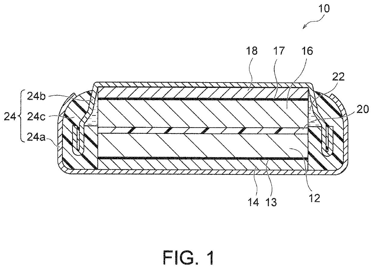
Provided is a lithium secondary battery including a positive electrode layer composed of a cobalt-containing lithium complex oxide sintered body, a negative electrode layer composed of a titanium-containing sintered body, a ceramic separator interposed between the positive electrode layer and the negative electrode layer and containing MgO, an electrolytic solution with which the positive electrode layer, the negative electrode layer, and the ceramic separator are impregnated, and an exterior body including a closed space, the closed space accommodating the positive electrode layer, the negative electrode layer, the ceramic separator, and the electrolytic solution, wherein the positive electrode layer, the ceramic separator, and the negative electrode layer are bonded together, and the interface between the negative electrode layer and the ceramic separator has a larger roughness than the interface between the positive electrode layer and the ceramic separator.

Description

CROSS-REFERENCE TO RELATED APPLICATIONS[0001]This application is a continuation application of PCT / JP2019 / 019176 filed May 14, 2019, which claims priority to Japanese Patent Application No. 2018-095782 filed May 17, 2018 and Japanese Patent Application No. 2019-061690 filed Mar. 27, 2019, the entire contents all of which are incorporated herein by reference.BACKGROUND OF THE INVENTION1. Field of the Invention[0002]The present invention relates to a lithium secondary battery.2. Description of the Related Art[0003]Lithium secondary batteries are widely used in various devices that require charging. In many existing lithium secondary batteries, a powder-dispersed positive electrode (so-called coated electrode) produced by applying a positive electrode mixture containing a positive electrode active material, a conductive agent, a binder, and the like, followed by drying, is employed.[0004]Such powder-dispersed positive electrodes generally contain a relatively large amount (e.g., about ...

Claims


Application Information

Patent Timeline
Patent Type & Authority Applications(United States)
IPC IPC(8): H01M10/0525H01M4/525H01M4/485H01M2/16H01M2/02H01M10/0585H01M50/409H01M50/489H01M50/491
CPCH01M10/0525H01M4/525H01M4/485H01M2004/021H01M2/02H01M10/0585H01M2/1646Y02E60/10Y02P70/50H01M50/437H01M50/434H01M50/46H01M4/0471H01M10/0427H01M4/1391H01M50/409H01M50/491H01M50/489H01M50/10H01M50/431
Inventor YURA, YUKINOBUOKADA, SHIGEKIOISHI, KENGO
Owner NGK INSULATORS LTD
Learn More