Communications System, Receiver Apparatus, Transmission Mode Proposal Method, and Program

a communication system and receiver technology, applied in the field of communication systems, can solve problems such as inability to follow a quick propagation path condition and insufficient correction

Inactive Publication Date: 2008-01-03
SONY CORP
View PDF5 Cites 34 Cited by
  • Summary
  • Abstract
  • Description
  • Claims
  • Application Information

AI Technical Summary

Benefits of technology

[0012] In carrying out the invention and according to a first embodiment thereof, there is provided a reception apparatus. This reception apparatus has a transmission mode table for holding, as transmission modes, a plurality of combinations of a modulating scheme and a coding ratio to be applied to the signal transmitted from the transmission apparatus, and a propagation path condition detecting block for detecting a condition of propagation path with the transmission apparatus. The reception apparatus further has a transmission mode extraction block for extracting a transmission mode transmitted from the transmission apparatus, and a threshold adjustment block for adjusting a threshold value of the propagation path condition at the time of selecting a transmission mode to be proposed next in accordance with a difference between the extracted transmission mode and a transmission mode proposed last. The reception apparatus still further has a transmission mode proposal block for selecting a proper transmission mode from among transmission modes held in the transmission mode table on the basis of a relation between the propagation path condition and the threshold value and proposing the selected transmission mode to the transmission apparatus. The above-mentioned novel configuration brings about an advantageous effect of adjusting a threshold value of the condition of propagation path at the time of selecting a transmission mode to be proposed next in accordance with a difference between the transmission mode proposed last and the transmission mode actually used.
[0015] In carrying out the invention and according to a second embodiment thereof, there is provided a reception apparatus. This reception apparatus has a transmission mode table for holding, as transmission modes, a plurality of combinations of a modulating scheme and a coding ratio to be applied to the signal transmitted from the transmission apparatus, and a propagation path condition detecting block for detecting a condition of propagation path with the transmission apparatus. The reception apparatus further has a retransmission probability prediction block for predicting a probability of retransmission of a signal to be transmitted next from a reception log of signals transmitted from the transmission apparatus, and a threshold adjustment block for adjusting a threshold of the propagation path condition at the time of selecting a transmission mode to be proposed next on the basis of the retransmission probability. The reception apparatus further has a transmission mode proposal block for selecting a proper transmission mode from among transmission modes held in the transmission mode table on the basis of a relation between the propagation path condition and the threshold value and proposing the selected transmission mode to the transmission apparatus. This novel configuration brings about an advantageous effect of adjusting a threshold value of the propagation path condition at the time of selecting a transmission mode to be propsosed next in accordance with a retransmission probability predicted from a reception log of signals transmitted from the above-mentioned transmission apparatus.
[0018] As described and according to the invention, excellent effects that the index for the selection of a transmission mode so as to correctly follow changes of propagation path conditions is adjusted can be provided.

Problems solved by technology

However, a transmission mode proposed by the receiver side does not always match a transmission mode determined by the transmission mode for actual use, so that it is possible for the correction not to be made sufficiently.
In addition, from the viewpoint of QoS (Quality of Service), the related-art technology is effective for the adjustment of a transmission mode in accordance with a required error ratio of the data to be transmitted, but, because this requires a long-term observation, the related-art technology presents a problem of the inability of following a quick propagation path condition.

Method used


Image

  • Communications System, Receiver Apparatus, Transmission Mode Proposal Method, and Program
  • Communications System, Receiver Apparatus, Transmission Mode Proposal Method, and Program
  • Communications System, Receiver Apparatus, Transmission Mode Proposal Method, and Program

Examples


Embodiment Construction

[0032] This invention will be described in further detail by way of embodiments thereof with reference to the accompanying drawings.

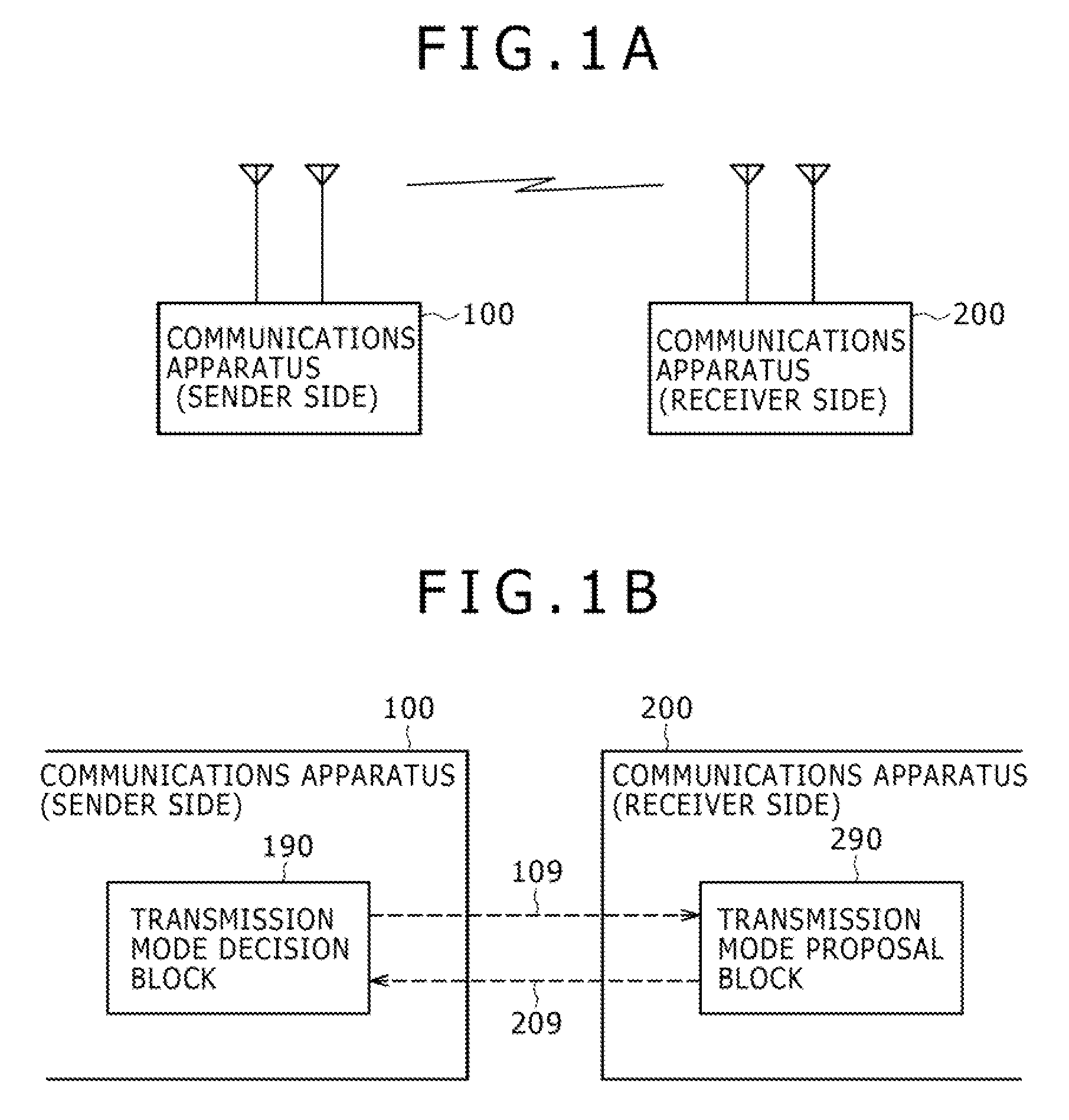
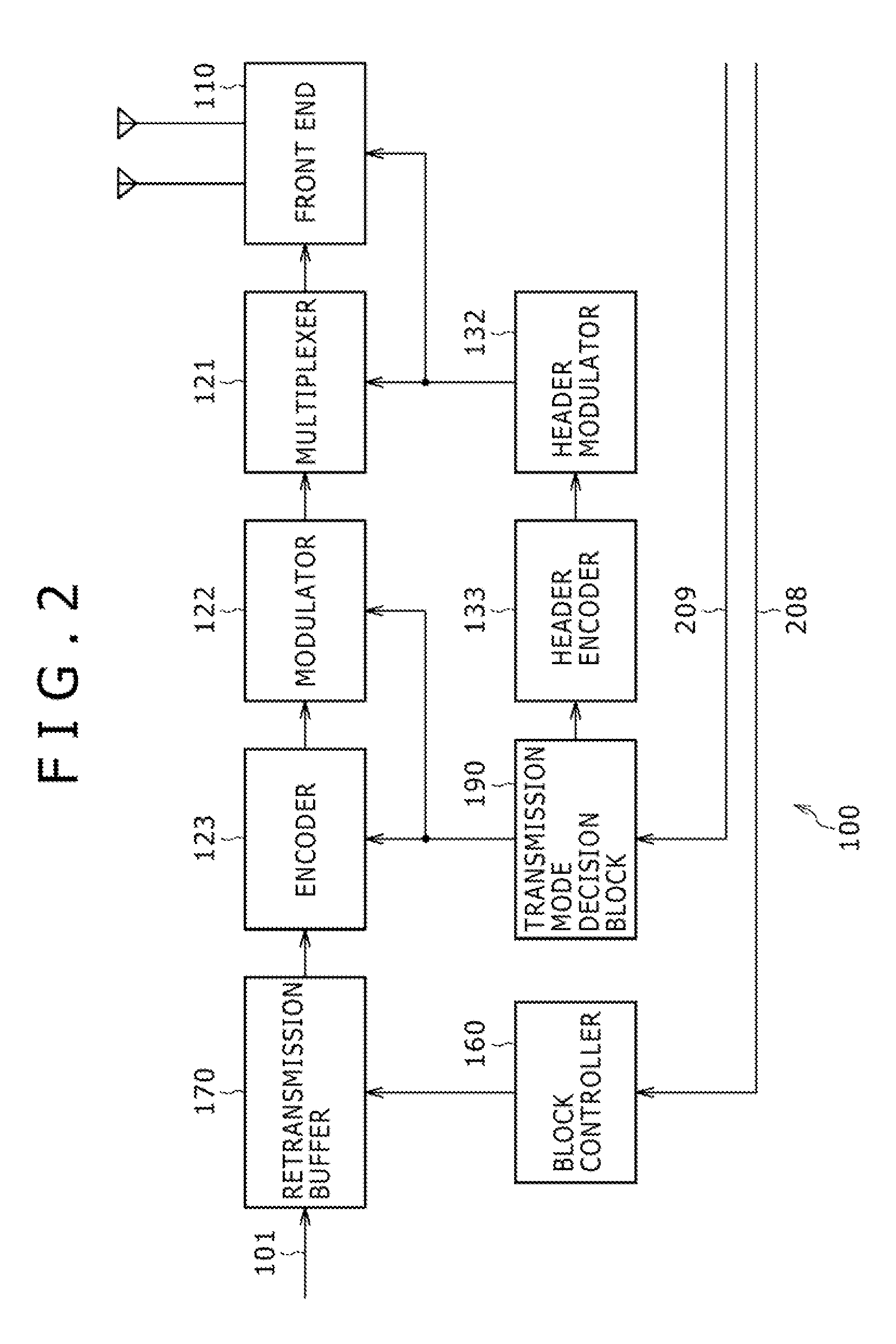
[0033] Now, referring to FIG. 1, there is shown an exemplary overall configuration of a communications system practiced as one embodiment of the invention. This communications system is composed of at least two units of communications apparatuses. FIG. 1A shows a system having at two communications apparatuses 100 and 200 as a minimum configuration. For the purpose of convenience, the communications apparatus 100 is on the sender side and the communications apparatus 200 is on the receiver side; actually, however, these two apparatuses are substantially the same in configuration because each executes both transmission and reception.

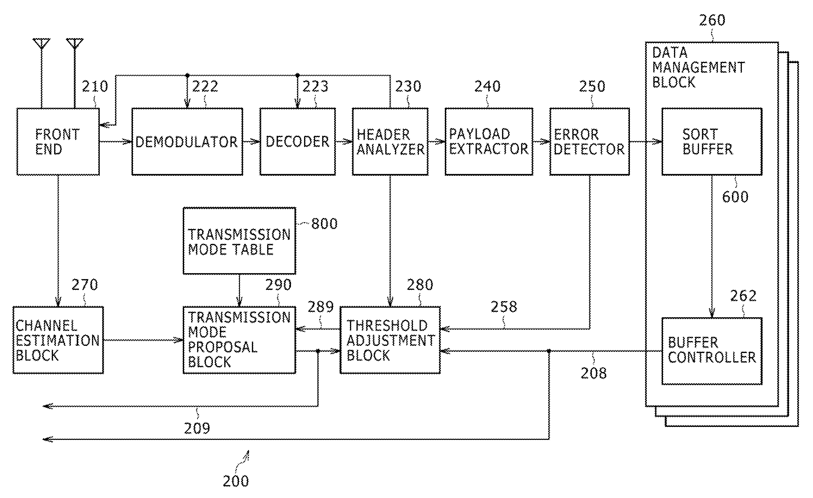
[0034] It should be noted that, in the present embodiment of the invention, the communications apparatus 100 and the communications apparatus 200 are assumed to use the MIMO (Multiple Input Multiple Output) scheme. Namely, ...


PUM


Abstract

A communications system has a transmission apparatus for transmitting a signal and a reception apparatus for receiving the signal. The reception apparatus includes: a transmission mode table; a propagation path condition detecting block; a transmission mode extraction block; a threshold adjustment block; and a transmission mode proposal block.

Description

CROSS REFERENCES TO RELATED APPLICATIONS [0001] The present invention contains subject matter related to Japanese Patent Application JP 2006-155554 filed in the Japan Patent Office on Jun. 5, 2006, the entire contents of which being incorporated herein by reference. BACKGROUND OF THE INVENTION [0002] 1. Field of the Invention [0003] The present invention relates to a communications system and, more particularly, to a communications system in which a transmission mode (modulating and coding ratio) in a transmitter apparatus is proposed by a receiver apparatus and a processing method therefor, and a computer program for having a computer execute this method. [0004] 2. Description of the Related Art [0005] With communications apparatuses based on wireless LAN (Local Area Network) and mobile communication, for example, sol-called adaptive transmission is proposed in which transmission modes are dynamically changed over in accordance with propagation path situations so as to enhance tran...

Claims


Application Information

Patent Timeline
Patent Type & Authority Applications(United States)
IPC IPC(8): H04B7/005H04J99/00
CPCH04B7/04H04L1/0003H04L1/0009H04L1/0015H04L1/0016H04B17/382H04L1/0025H04W52/262H04B17/24H04B17/309H04L1/0021
Inventor ITOH, KATSUTOSHI
Owner SONY CORP
Why Eureka
Try Eureka