Vibratory plate

a technology of vibrating plate and valve knob, which is applied in the field of vibrating plate, can solve the problems of difficult to flush the outlet without extensive disassembly, difficult to reach the valve knob, and easy blockage of the outlet, so as to minimize the risk of blockage. , the effect of easy flushing

Active Publication Date: 2008-01-03
HUSQVARNA AB
View PDF10 Cites 19 Cited by
  • Summary
  • Abstract
  • Description
  • Claims
  • Application Information

AI Technical Summary

Benefits of technology

[0004]It is an object of the invention to provide a vibratory plate incorporating a sprinkler device that solves the above described problems. This is achieved in that the water outlet of the sprinkler is arranged for the release of water only to the middle of the channel and therefore only needs to comprise one or two openings. The total opening area of the outlet is allocated to a smaller number of openings than in known sprinkler devices and the individual openings are therefore designed with the largest possible area. The risk of blockage is accordingly minimized. The openings are integrated in the valve and can easily be flushed if necessary. The released water is guaranteed to be distributed along the entire length of the channel in that the channel is arranged at an angle. The operator can easily reach the valve knob with one hand without fully releasing the control handle with the other hand because the knob is placed on the top of the tank. Regulating the release of water is also simplified in that it is arranged in steps perceptible for the operator.

Problems solved by technology

This can cause the outlet to become very easily blocked by impurities in the water.
In such circumstances it is complicated to flush the outlets without extensive dismantling.
From an ergonomic point of view this is not a good position for the knob because the operator has to bend down a long distance to reach the knob.
There is a considerable risk that the operator will operate the valve by kicking the knob instead of bending down and in so doing damage the knob or adjacent components.
The positioning and execution also make it difficult for the operator to regulate the quantity of water released.
There is a considerable risk that the operator will not regulate the quantity of the water to be released to what is actually needed and will instead open the valve completely.
The result of this is that an unnecessary amount of time must be used to refill the tank with water.

Method used


Image

  • Vibratory plate
  • Vibratory plate
  • Vibratory plate

Examples


Embodiment Construction

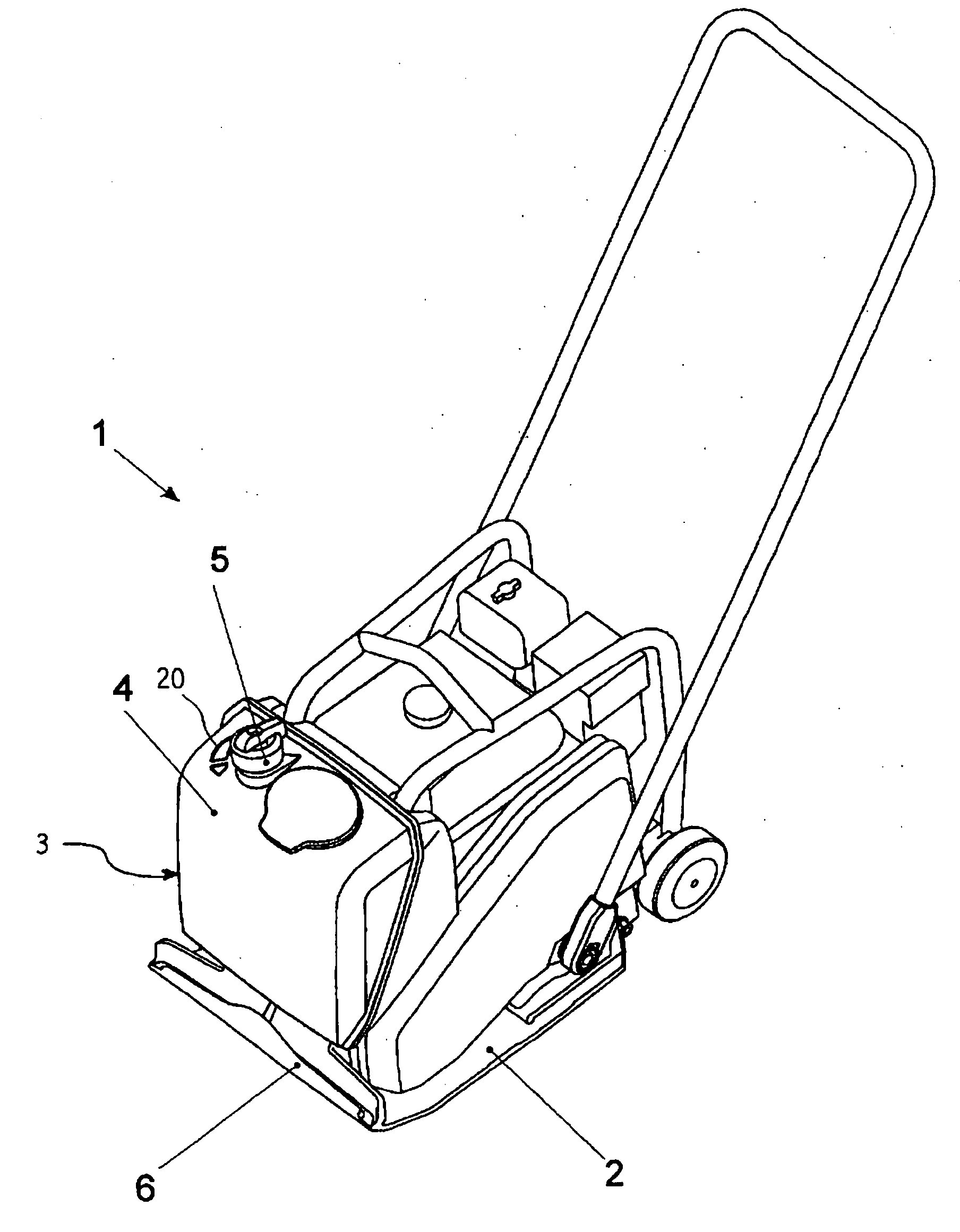
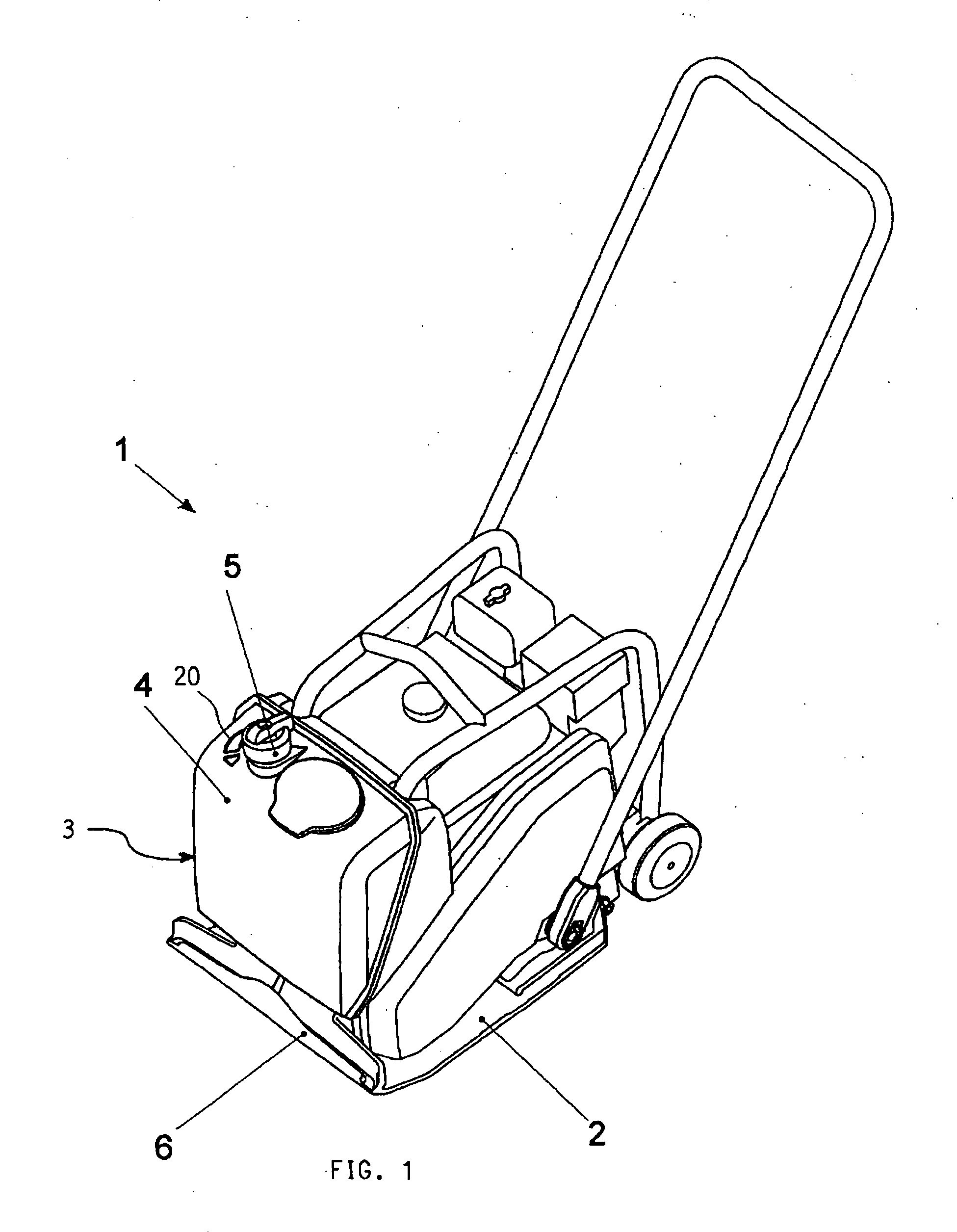
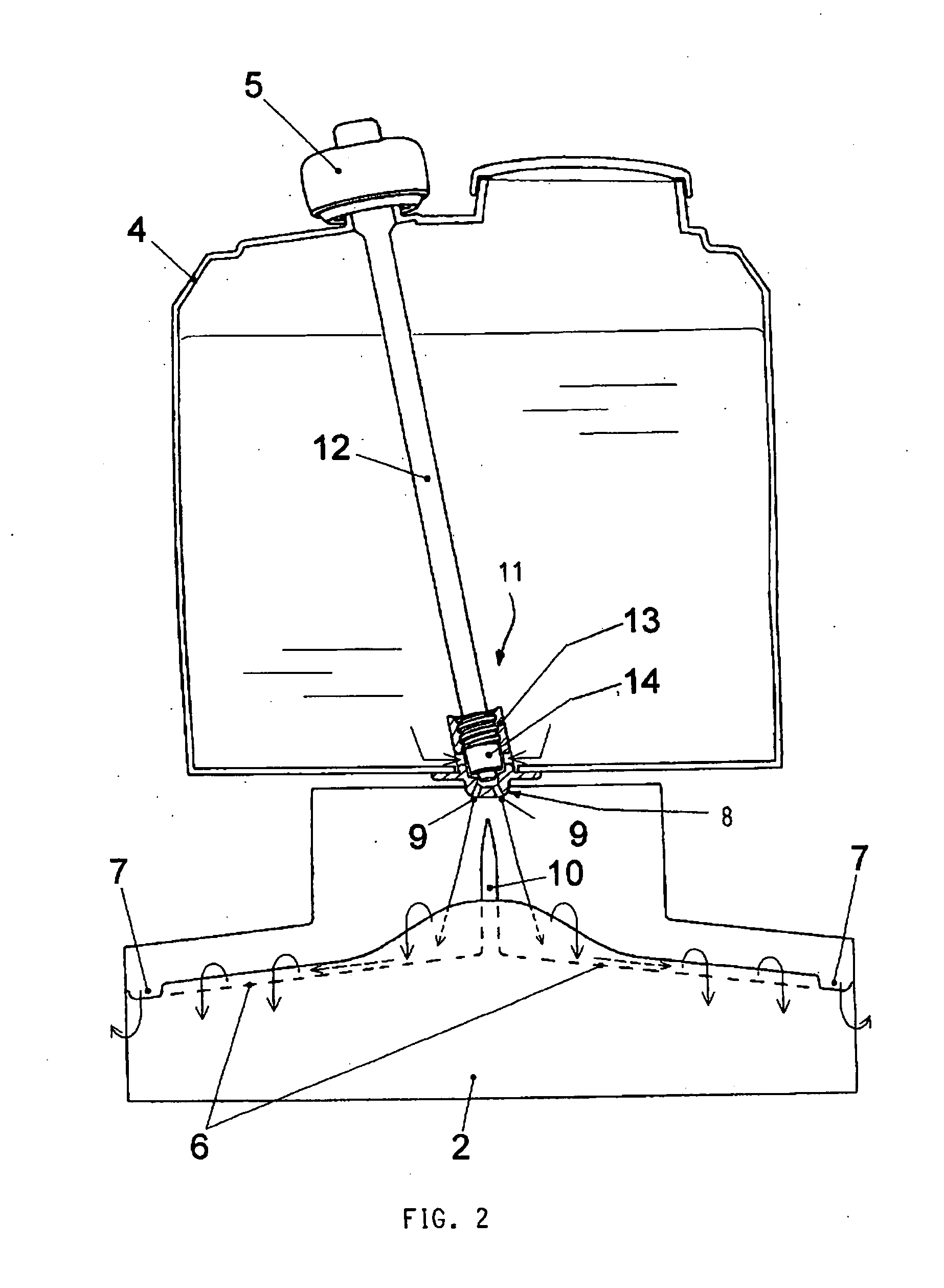
[0010]FIG. 1 shows a vibratory plate 1 with a base plate 2. The base plate 2 can be brought to vibrate to compact the underlying surface and to drive the vibratory plate 1 forward. The sprinkler device 3 is placed at the front of the vibratory plate 1 and comprises a water tank 4, a knob 5 and a channel 6 extending along the front edge of the base plate 2. The sprinkler device 3 also comprises a valve 11, a valve stem extension 12 and an outlet 8 for water shown in FIG. 2. The release of the water is controlled by the valve 11. The valve 11 is operated with the knob 5 via the valve stem extension 12 and can be actuated to close, open and regulate the release of water to the channel 6. When the released water reaches the channel 6, it is distributed along the entire length of the channel. The vibrations in the base plate 2 cause the water to be finely separated into droplets that gradually slide over the front wall of the channel 6 to the underside of the base plate 2 in the intended...


PUM


Abstract

A vibratory plate includes a sprinkler device (3) for wetting the underside of a base plate (2) of the vibratory plate (1). The vibratory plate also includes a water tank (4) and the sprinkler device (3) has an outlet (8) for passing the water, a valve (11) to control the release of water and a knob (5) for the operation of the valve. A channel (6) guides the released water and is arranged along the front edge of the base plate (2). The channel (6) is arranged with descending inclinations along and from the middle of its length and to both side edges of the base plate (2). The outlet (8) is only arranged for the release of water to the middle of the channel (6).

Description

CROSS REFERENCE TO RELATED APPLICATION[0001]This application claims priority of Swedish patent application no. 0601448-4, filed Jul. 3, 2006, the entire content of which is incorporated herein by reference.FIELD OF THE INVENTION[0002]The invention relates to a vibratory plate having a sprinkler device. The sprinkler device is less sensitive to impurities than previously known devices and is therefore more operationally reliable. The sprinkler device is also operated with better ergonomics than previously known devices. The device is suitable for light vibration plates used for the compaction of asphalt, gravel, stones, soil or macadam.BACKGROUND OF THE INVENTION[0003]During vibratory compaction of asphalt with a vibratory plate, the underside of the base plate is continually wetted to avoid the adhesion of asphalt. Water is normally used for this wetting, however, emulsions can also be used. On page 13 of the manual: “Mikasa SERIES MODEL MVC-88GH / GHW ONE-WAY PLATE COMPACTOR”, “Revis...

Claims


Application Information

Patent Timeline
Patent Type & Authority Applications(United States)
IPC IPC(8): E01C19/32E01C19/35
CPCE01C19/38E01C19/238E02D3/068
Inventor PERSSON, GERTHEDLUND, GUNNAR
Owner HUSQVARNA AB
Why Eureka
Try Eureka