Electromagnetic lock

a technology of electromagnetic locks and solenoid devices, applied in the field of electronic locks, can solve the problems of complex adjustment procedure of solenoid device position, inability of users to adjust the operation mode by themselves, and complicated inventory control and management costs of manufacturers to fabricate these two types of magnetic locks

Inactive Publication Date: 2008-01-10
LIAO LI SHIH
View PDF3 Cites 27 Cited by
  • Summary
  • Abstract
  • Description
  • Claims
  • Application Information

AI Technical Summary

Benefits of technology

[0007] It is a primary object of the invention to eliminate the above-mentioned drawbacks and to

Problems solved by technology

It greatly complicates the manufacturer's inventory control and the related management cost to fabricate these two types of magnetic locks.
This solenoid device position adjustment procedure is complicated.
Accordingly, it is not possible for the user to adjust the operation mode by himself.
As a result, the current is applied to the solenoid device 62 all day long even

Method used


Image

  • Electromagnetic lock
  • Electromagnetic lock
  • Electromagnetic lock

Examples


Embodiment Construction

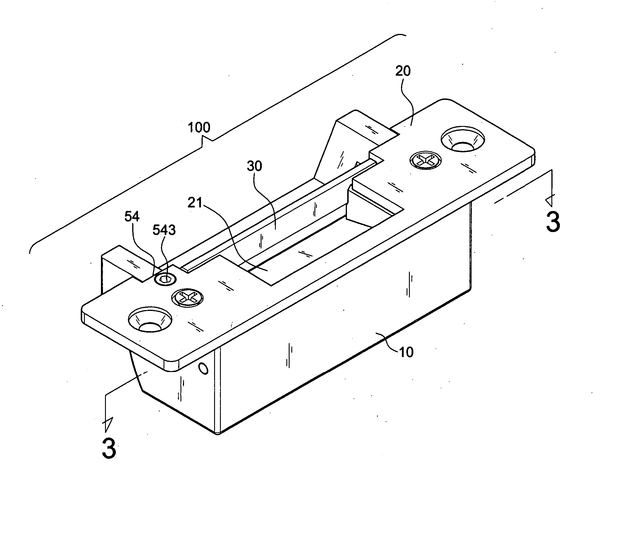
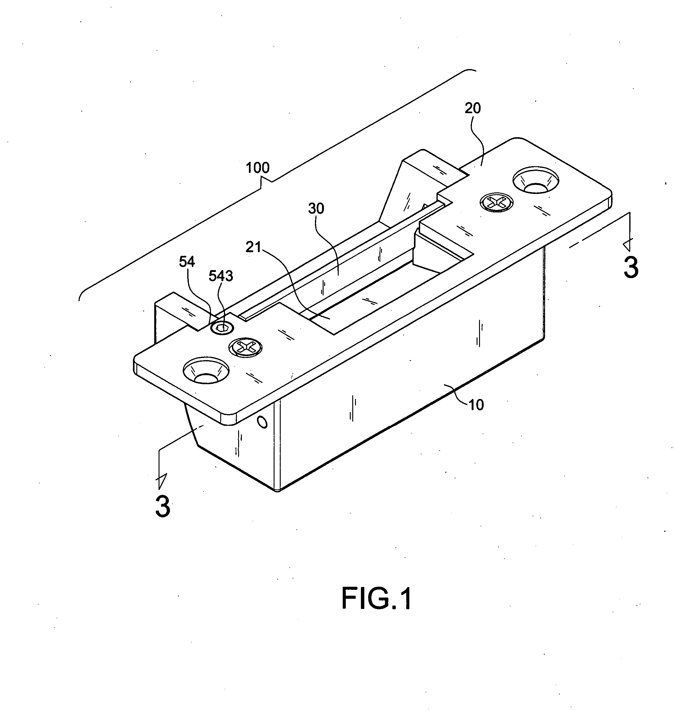
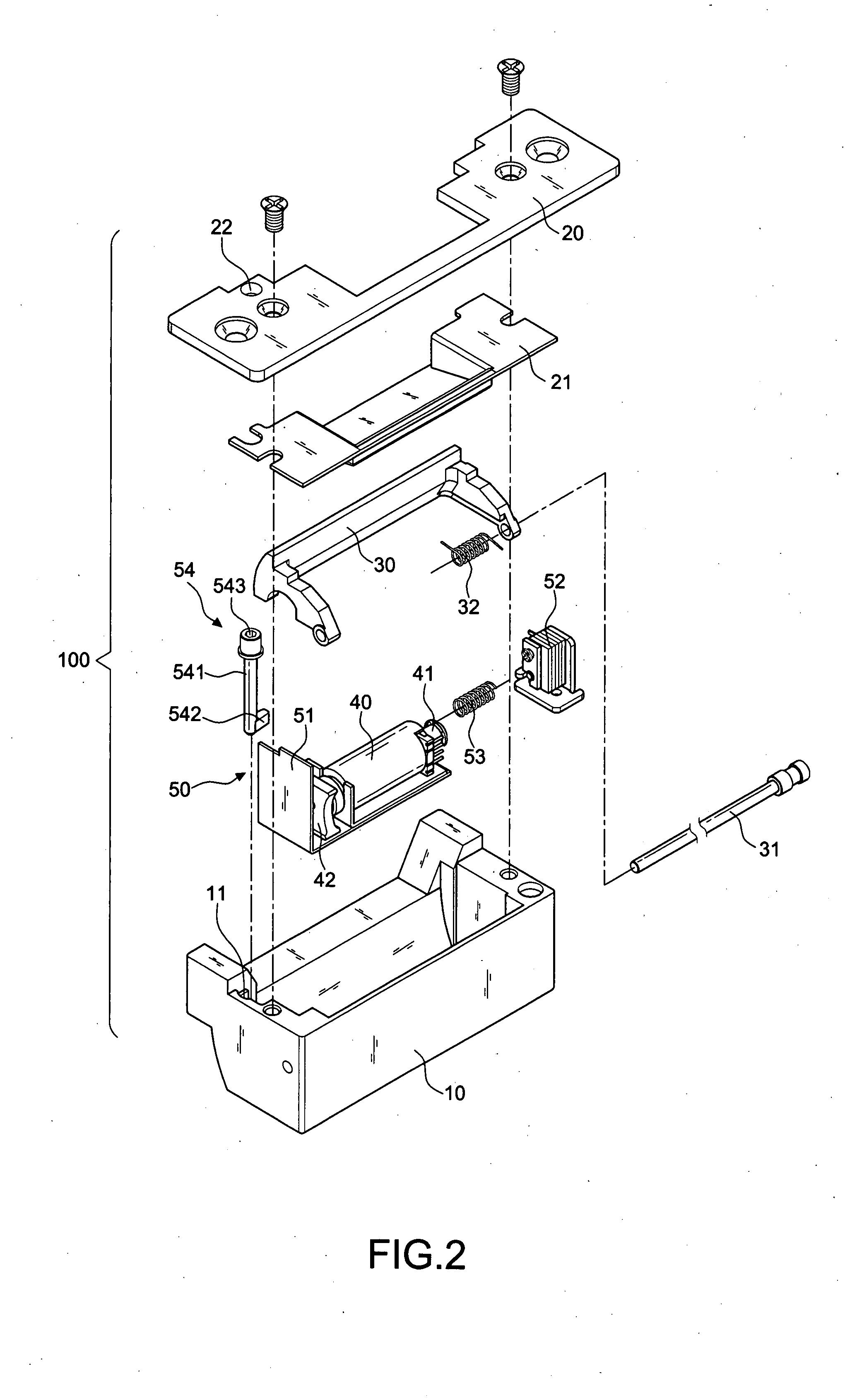
[0034] First of all, referring to FIGS. 1 and 2, an electromagnetic lock 100 in accordance with the invention includes a receiving space defined by a housing 10 and a cover 20. A lock catch 30, an solenoid valve 40, an adjusting unit 50, and a decoration plate 21 are received within the receiving space.

[0035] The lock catch 30 is pivotally coupled to the housing 10 by a positioning shaft 31 in match of a torque maintaining element 32 like a torsion spring.

[0036] The solenoid valve 40 includes a movable shaft 41. An end stop 42 adapted to the lock catch 30 is disposed at a position opposing to the movable shaft 41. The position of the end stop 42 is changeable when a voltage is applied to the solenoid valve 40, thereby determining whether or not the lock catch 30 is engaged into the bottom of the housing 10.

[0037] The adjusting unit 50 includes an L-shaped slide carriage 51 to receive the solenoid valve 40. A restoring spring 53 is interposed between the L-shaped slide carriage 51...


PUM


Abstract

An electromagnetic lock with a receiving space defined by a housing and a cover, comprising a lock catch, an solenoid valve, an adjusting unit, and a decoration plate all of which are received within the receiving space. The lock catch is pivotally coupled to a housing by a positioning shaft in match of a torque maintaining element. The solenoid valve includes a movable shaft and an end stop adapted to the lock. The position of the end stop is changeable when a voltage is applied to the solenoid valve, thereby determining whether or not the lock catch is engaged into the bottom of the housing. The adjusting unit includes an slide carriage to receive the solenoid valve. A restoring spring is interposed between the slide carriage and a fixing piece. The adjusting unit further includes an adjusting element with an operating head sitting on a free side of the cover for controlling the position switching of the slide carriage, thereby controlling the position of the solenoid valve carried by the slide carriage relative to the lock catch. Accordingly, the electromagnetic lock may be brought into an unlocked or locked state.

Description

BACKGROUND OF THE INVENTION [0001] 1. Field of the Invention [0002] The present invention relates to locks and more particularly, to an electromagnetic lock that can be conveniently and selectively adjusted between two reversed modes, allowing the magnetic lock to be locked or unlocked when electrically connected. [0003] 2. Description of the Related Art [0004] Conventional magnetic locks include two types, the type that is locked when electrically connected, and the type that is unlocked when electrically connected. It greatly complicates the manufacturer's inventory control and the related management cost to fabricate these two types of magnetic locks. Taiwan patent publication no. 384904, filed by the present inventor on Apr. 14, 1998, discloses a magnetic lock, which has the electromagnetic valve adjustable between two positions to have the magnetic lock be locked or unlocked when electrically connected. [0005] U.S. Pat. No. 6,299,225 issued on Oct. 9, 2001, discloses a magnetic...

Claims


Application Information

Patent Timeline
IPC IPC(8): E05B47/08
CPCE05B47/0047E05B2047/0077E05B2047/0074E05B63/0065Y10T70/7904
Inventor LIAO, LI-SHIH
Owner LIAO LI SHIH
Why Eureka
Try Eureka