Inkjet recording apparatus and air removal method therefor

a technology of air removal and recording apparatus, which is applied in the direction of printing, other printing apparatus, etc., can solve the problems of air and ink whose viscosity is increased, the ink discharged from the inkjet head can be disturbed, and the ink is sucked and not used in the recording,

Active Publication Date: 2008-01-10
BROTHER KOGYO KK
View PDF16 Cites 12 Cited by
  • Summary
  • Abstract
  • Description
  • Claims
  • Application Information

AI Technical Summary

Benefits of technology

[0006]In the inkjet recording apparatus, suction means connected to the air vent passage can remove the air remaining in the ink tank for a shorter time. However, in the case where the air existing in an ink supply channel system such as a tube located on an up

Problems solved by technology

However, a larger amount of ink which is sucked and not used in the recording becomes wasted.
In the case where the ink flows into the su

Method used


Image

  • Inkjet recording apparatus and air removal method therefor
  • Inkjet recording apparatus and air removal method therefor
  • Inkjet recording apparatus and air removal method therefor

Examples


Embodiment Construction

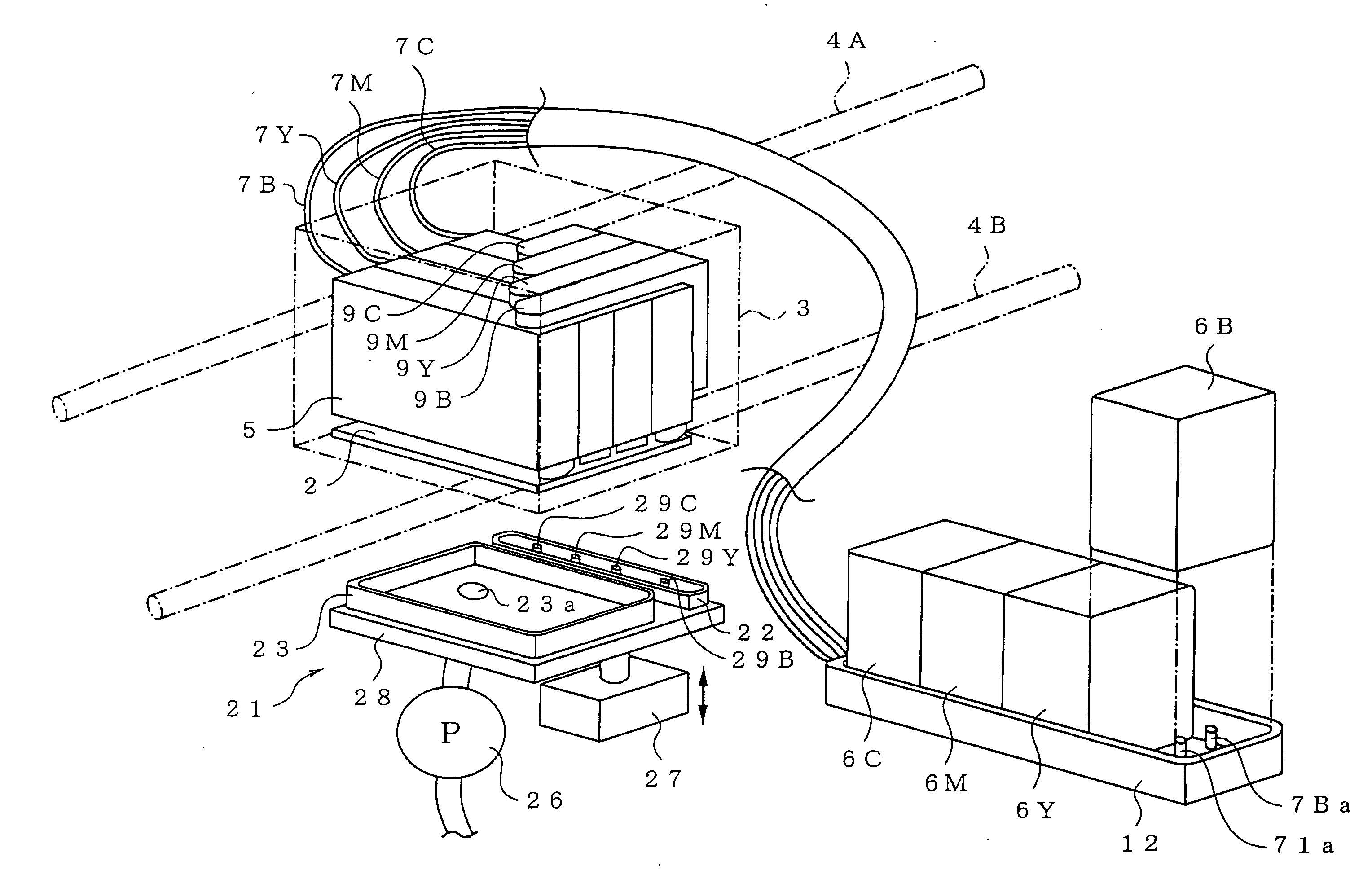
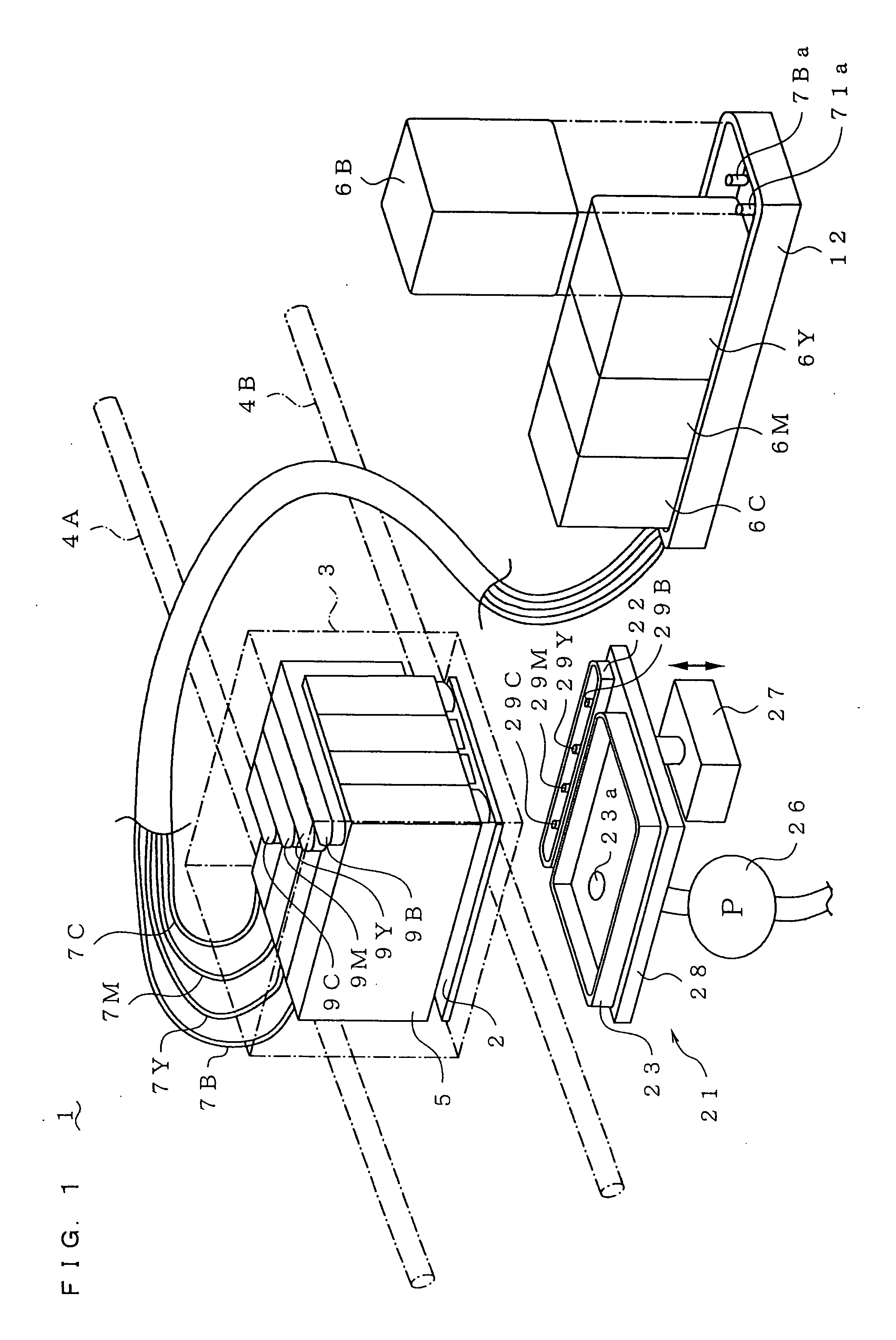
[0016]An embodiment of the invention will be described below with reference to the drawings. Each suffix of B, Y, M, and C added to the numeral indicates that the numeral is used for each of black, yellow, magenta, and cyan inks.

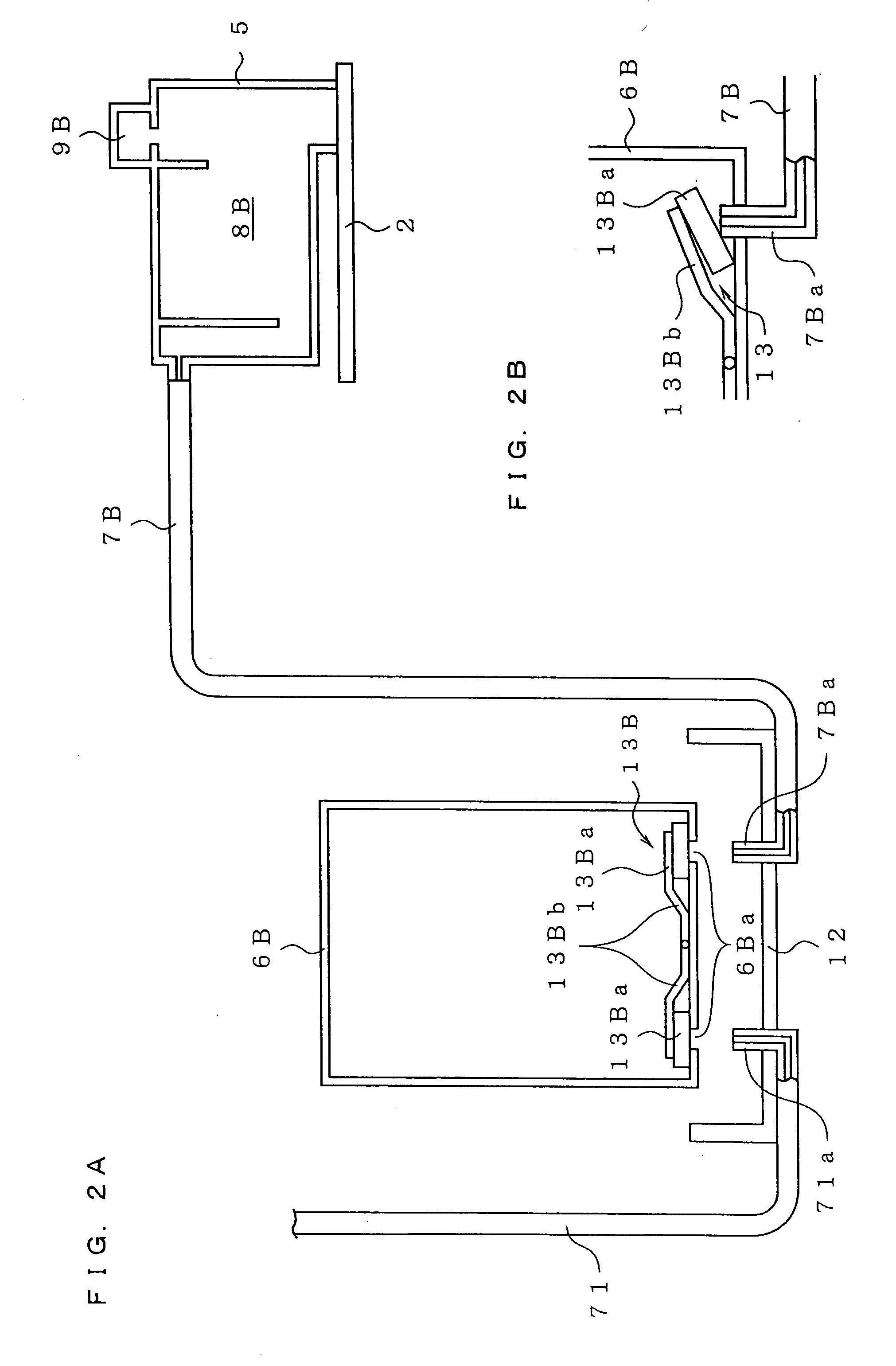
[0017]As shown in FIGS. 1 and 2A, an inkjet recording apparatus 1 includes an inkjet head 2. The inkjet head 2 is retained by a head holder 3, and the head holder 3 is supported while being relatively movable to a recording medium. The inkjet head 2 has a group of nozzles which discharge plural kinds of inks (see 2B, 2Y, 2M, and 2C in FIG. 3). Specifically, the head holder 3 is supported while being reciprocally movable along guide rails 4A and 4B extended in a direction orthogonal to a recording-medium feed direction by drive means. An ink tank 5 is mounted on the head holder 3 to supply the ink to the inkjet head 2.

[0018]The ink tank 5 includes ink reservoir chambers 8B, 8Y, 8M, and 8C (see FIG. 3) and air vent passages 9B, 9Y, 9M, and 9C. The plural kinds...


PUM


Abstract

There is provides an inkjet recording apparatus comprising: an inkjet head held in a head holder; and an ink tank mounted on the head holder. The ink tank has an ink chamber, a path for communicating the chamber with atmosphere, and an exit valve to open and close the path. The apparatus further comprises: an ink cartridge arranged below the ink tank for supplying the ink to the ink chamber through a channel; an operating member for opening and closing the exit valve; a ink transfer device; and a controller. The controller performs controls of causing the operating member to open the exit valve such that an atmosphere pressure affects an inside of the ink chamber, and such that the ink both in the chamber and in the channel returns to the ink cartridge through the channel; and causing the device to fill the chamber.

Description

CROSS-REFERENCE OF RELATED APPLICATION[0001]This non-provisional application claims priority under 35 U.S.C. §119(a) on Patent Application No. 2006-185293 in Japan on Jul. 5, 2006, the entire contents of which are hereby incorporated by reference.BACKGROUND[0002]1. Technical Field[0003]The present invention relates to an inkjet recording apparatus and an air removal method therefor.[0004]2. Description of Related Art[0005]A known inkjet recording apparatus (for example, see Japanese Patent Application Laid-Open No. 2004-255861, FIG. 9) includes a head holder which retains an inkjet head and is supported relatively movable with respect to a recording medium. An ink tank is mounted on the inkjet head for supplying ink. An ink cartridge which supplies the ink to the ink tank through a tube is arranged below the ink tank and outside the head holder. In the recording apparatus having the above configuration, the ink is supplied from the ink cartridge to the ink tank through the tube. The...

Claims


Application Information

Patent Timeline
IPC IPC(8): B41J2/19
CPCB41J2/19B41J2/17509
Inventor SAKURAI, HISAKIUSUI, TAKAMASA
Owner BROTHER KOGYO KK
Why Eureka
Try Eureka