Apparatus and method for air removal in tillage implements using three way valves

a technology of tillage implements and air removal methods, applied in the field of agricultural implements, can solve the problems of reducing the efficiency and speed with which the particular task is accomplished, the difficulty of having a level positioning of the implement, and the criticality of having a uniform and level tool contact with the soil, etc., and achieves the effect of effective air removal

Active Publication Date: 2016-06-14
CNH IND CANADA
View PDF22 Cites 6 Cited by
  • Summary
  • Abstract
  • Description
  • Claims
  • Application Information

AI Technical Summary

Benefits of technology

[0010]An advantage of the present invention is a more effective air removal in systems that synchronize multiple sections of a farm tillage implement.
[0011]In one form, the invention is an agricultural implement spanning a lateral distance relative to a forward direction, the implement including a plurality of carrier frames, each for supporting a plurality of soil engaging tools. At least one supporting element is carried by each carrier frame for variably positioning the carrier frame relative to the soil. A hydraulic actuator has a housing, in which a piston is displaceable and an output shaft connected thereto variably extending from the actuator housing and connected between each supporting element and respective carrier frame for varying the position of the respective carrier frame relative to the soil, each piston having a land to permit flow past the piston when the actuator output shaft is fully extended. A sensor determines the displacement of the output shaft relative to the actuator housing of each said actuator. A source of pressurized hydraulic fluid is provided to a hydraulic control unit receiving pressurized fluid and directing pressurized hydraulic fluid to the actuators to move the actuators independently in response to a signal input. An electronic control unit (ECU) establishes a desired input signal and compares it to the signal from each sensor to send a resultant signal to the hydraulic control unit for varying the position of each actuator output shaft to reach the signal input. A pair of hydraulic lines extend from the hydraulic control unit for connection with the actuators. Valves are controllable by the ECU for individually selectively bypassing or connecting each actuator to the hydraulic control unit, whereby the actuators may be controlled individually or in unison, the valves being connected by a common line. The ECU is controllable to fully extend the output shaft of one of the actuators and block other actuators from the hydraulic system while flowing hydraulic fluid through the valve common line and the one actuator past the land therein to remove air, the ECU being controllable to subsequently also extend the next actuator fully and flow hydraulic fluid through the next actuator and common line to remove air from the next actuator and, when air is removed from all subsequent actuators and common lines connecting the valves to provide a series connection therebetween.
[0012]In another form, the invention is a method of air removal for an agricultural implement including a plurality of articulated carrier frames, each for supporting a plurality of soil engaging tools and having at least one supporting element carried by the carrier frame for variably positioning the carrier frame relative to the soil. Hydraulic actuators are provided for each carrier frame with each actuator having a housing in which a piston is displaceable and output shaft connected thereto variably extending from the actuator housing and connected between the supporting elements and the carrier frame for setting the position of the carrier frame relative to the soil. A hydraulic control system applies pressurized hydraulic fluid to both sides of each piston with the pistons having a land so that when the output shaft is fully extended the piston permits hydraulic flow past the piston. Valves are associated with each actuator to permit flow through the actuators either in series or locking the valves from the system with the valves being connected to one another by a common line and one of the valves being closest to the hydraulic control unit. The method includes the steps of fully extending the output shaft of one of the actuators and locking other actuators from the hydraulic system. Thereafter, hydraulic fluid is passed through the valve common line and the one actuator to remove air therein. Subsequently, the adjacent actuator to the one actuator is extended fully and hydraulic fluid flows through the next actuator and the common line to remove therein. Subsequently, when air is removed from all subsequent actuators and common lines, the valves are set to connect the actuators in series for movement in unison.

Problems solved by technology

When the span increases to realize greater efficiency and speed, the criteria of having a uniform and level tool contact with the soil becomes extremely critical.
The need to have a level positioning of the implement is made more challenging with the use of hydraulic actuators which control the depth of penetration of the disk blades or other tools.
However, this adds an additional step to the operation, particularly in the field, thereby decreasing the efficiency and speed with which the particular task is accomplished.

Method used


Image

  • Apparatus and method for air removal in tillage implements using three way valves
  • Apparatus and method for air removal in tillage implements using three way valves
  • Apparatus and method for air removal in tillage implements using three way valves

Examples


Embodiment Construction

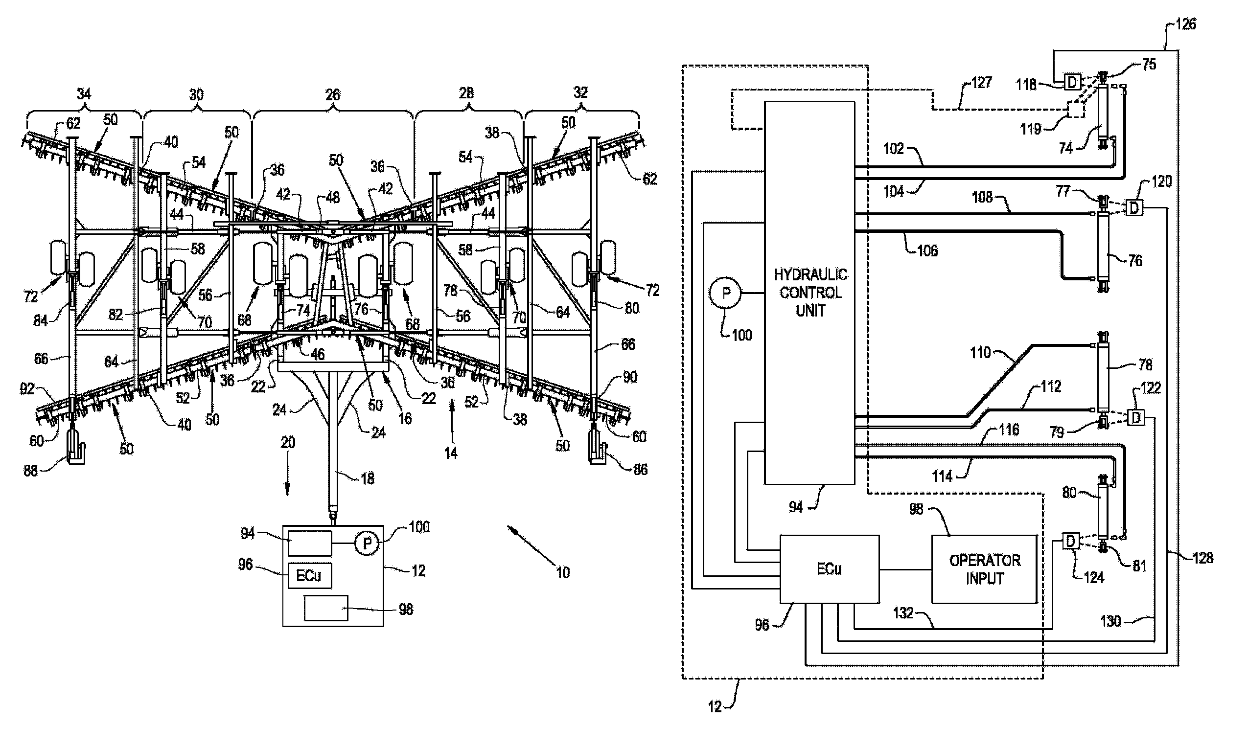
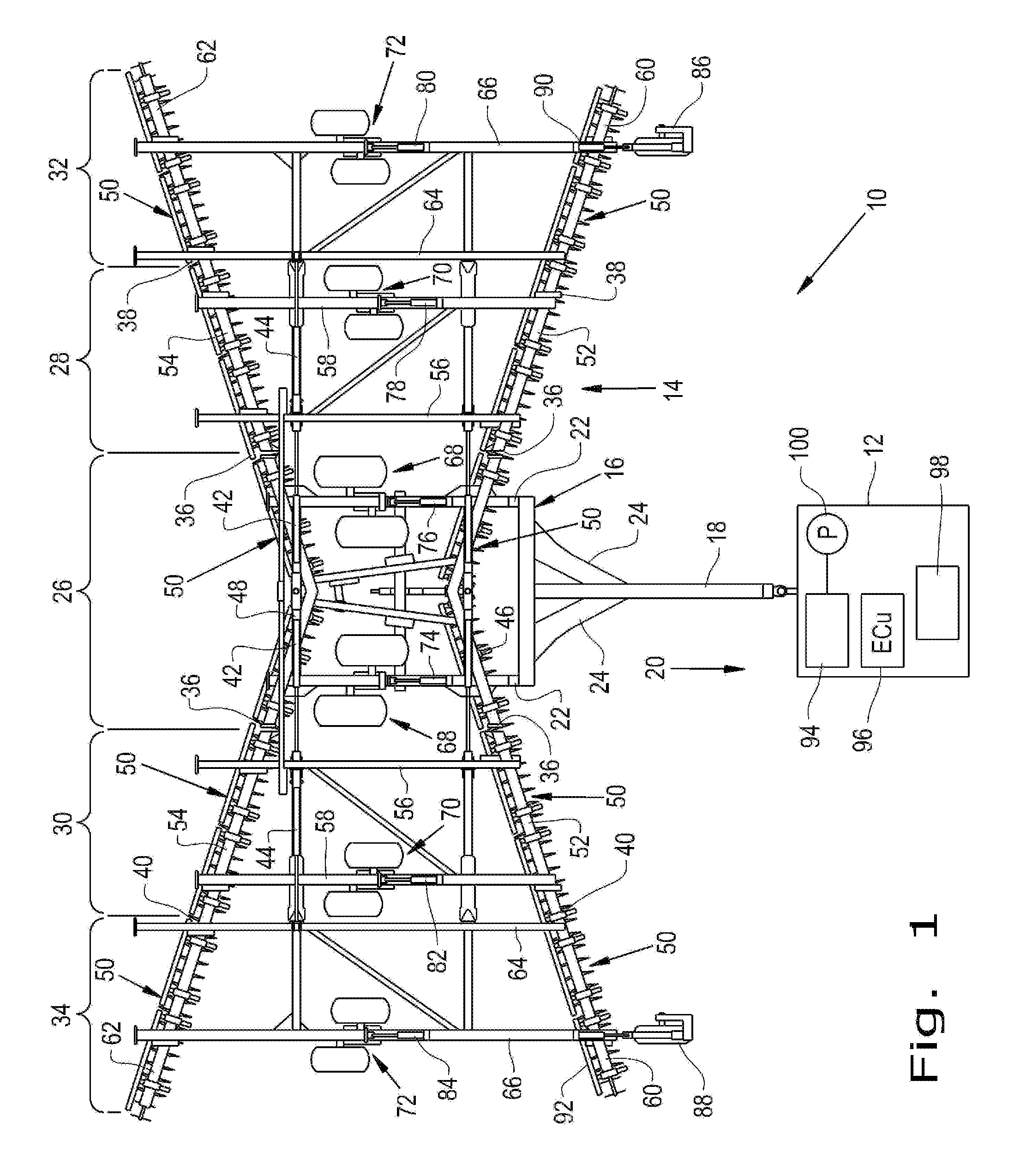
[0020]Referring now to the drawings, and more particularly to FIG. 1, there is shown a tillage apparatus 10 which generally includes a tractor 12 shown schematically and an agricultural tillage implement 14 for tilling the soil prior to seeding. It should be noted that many different tools may be employed with the tillage implement 14 beyond the embodiment shown.

[0021]Agricultural tillage implement 14 is configured as a multi-section field disk ripper 14, and includes a carriage frame assembly 16. Carriage frame assembly 16 is the section that is directly towed by a traction unit, such as agricultural tractor 12. Carriage frame assembly 16 includes a pull hitch 18 generally extending in a travel direction 20, and forward and aft oriented carrier frame members 22 which are coupled with and extend from pull hitch 18. Reinforcing gusset plates 24 may be used to strengthen the connection between pull hitch 18 and carrier frame members 22.

[0022]The tillage implement 14 has a center secti...


PUM


Abstract

Air is removed from an hydraulic system for an agricultural implement supporting a plurality of gangs of disk blades extending generally laterally relative to a forward travel direction. The implement has carrier frames pivotally connected to wheel assemblies for controlling the height of the carrier frames relative to the ground through hydraulic actuators acting on the wheel assemblies. The hydraulic control unit enables independent and individual control of each actuator. An electronic control unit (ECU) controls three way valves associated with each actuator so that they may be operated in unison or individually. Hydraulic fluid is passed through the most remote actuator first and then actuators closer to the hydraulic control unit to remove air.

Description

CROSS REFERENCE TO RELATED APPLICATIONS[0001]This is a non-provisional application based upon U.S. provisional patent application Ser. No. 61 / 914,678, entitled “APPARATUS AND METHOD FOR AIR REMOVAL IN TILLAGE IMPLEMENTS USING THREE WAY VALVES”, filed Dec. 11, 2013, which is incorporated herein by reference.BACKGROUND OF THE INVENTION[0002]1. Field of the Invention[0003]The present invention relates to farm implements, and, more particularly, to systems and methods for maintaining such implements level relative to the soil.[0004]2. Description of the Related Art[0005]In the continuing quest for providing greater efficiency in the operation of farm implements, machines have been constructed to have ever increasing lateral spans relative to a tractor or central unit propelling the unit over a field. When the span increases to realize greater efficiency and speed, the criteria of having a uniform and level tool contact with the soil becomes extremely critical. Equipment with significant...

Claims


Application Information

Patent Timeline
Patent Type & Authority Patents(United States)
IPC IPC(8): A01B63/22A01B21/08
CPCA01B63/22A01B21/083
Inventor HENRY, JAMES W.
Owner CNH IND CANADA
Why Eureka
Try Eureka