Image encoding/decoding method and apparatus

Inactive Publication Date: 2008-01-10
SAMSUNG ELECTRONICS CO LTD
View PDF10 Cites 39 Cited by
  • Summary
  • Abstract
  • Description
  • Claims
  • Application Information

AI Technical Summary

Benefits of technology

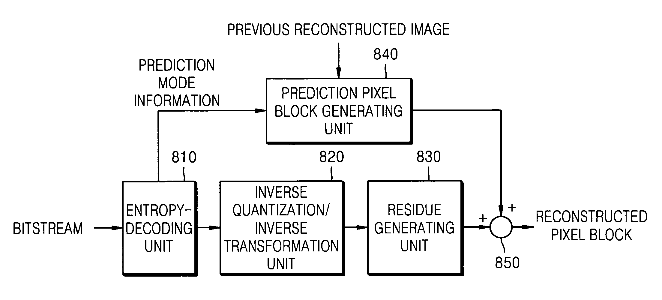
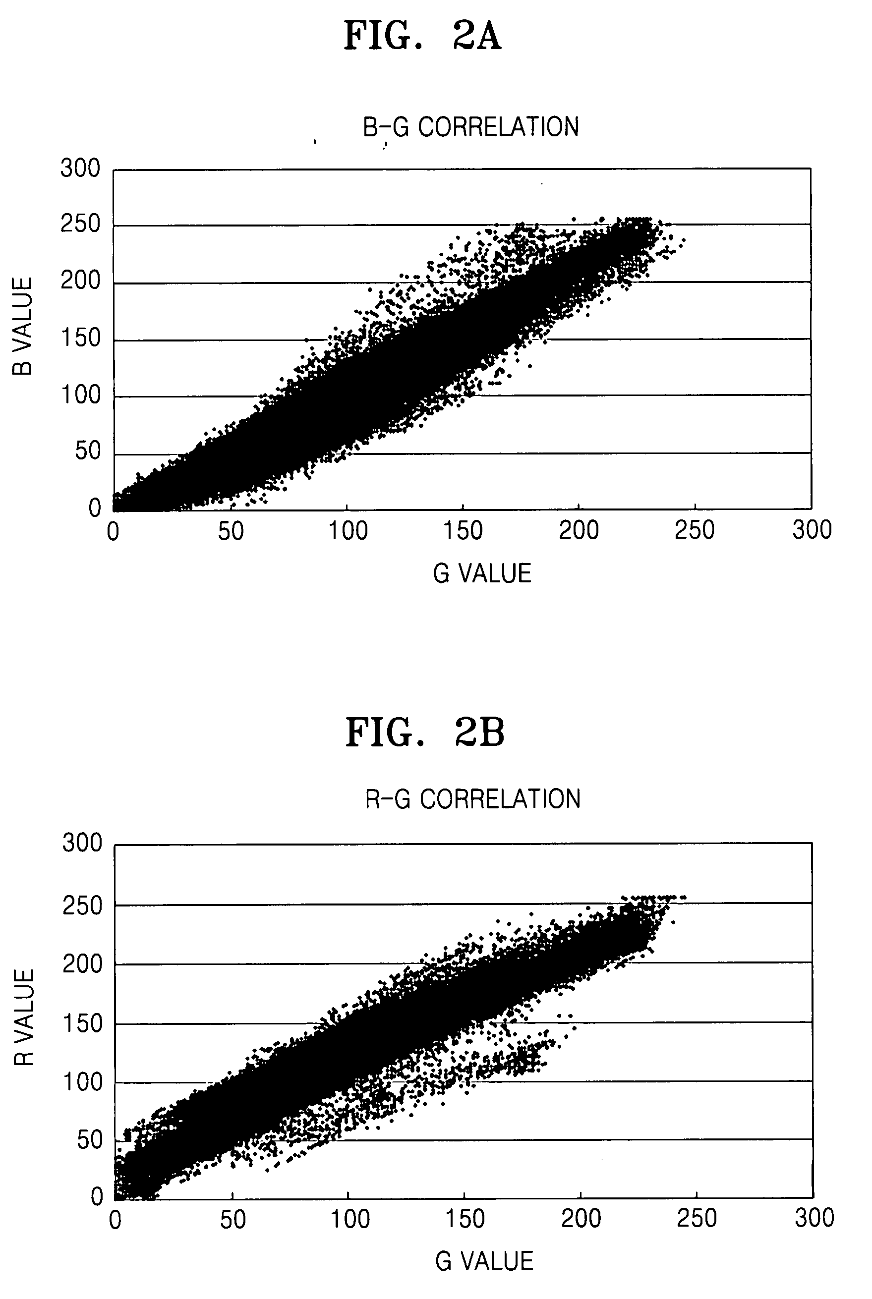
[0008]The present invention provides an image encoding/decoding method and apparatus, in which a residue of one of a plurality of color component images constituting a color image is predicted from anot

Problems solved by technology

However, since 1/4 sampling of U (or Cb) and V (or Cr) components in a YUV (or YCbCr) 4:

Method used


Image

  • Image encoding/decoding method and apparatus
  • Image encoding/decoding method and apparatus
  • Image encoding/decoding method and apparatus

Examples


Embodiment Construction

[0027]Hereinafter, exemplary embodiments of the present invention will be described in detail with reference to the accompanying drawings.

[0028]Terms used to explain the exemplary embodiments of the present will be defined.

[0029]A residue is defined as a difference between an original input image and a predicted image. When a color image comprises an R color component image, a G color component image, and a G color component image, residues of the color component images, AR, AG, and AB, are defined as follows;

ΔR=R−Rp

ΔG=G−Gp

ΔB=B−Bp   (1)

[0030]In equation (1), R, G and B represent original input images of the color components, and Rp, Gp and Bp represent predicted images of the color components.

[0031]A first residue block is defined as a block of which pixels are comprised of differences between the original input block and the predicted block. Actually, the first residue block is identical with the residue block in a related art.

[0032]A second residue block is defined as a block of...


PUM


Abstract

Image residue encoding and decoding methods and apparatuses are provided. In this method, a residue of a color component image is predicted from another color component image using a correlation between residues of the color component images, wherein the residues correspond to differences between input images and prediction images of the respective color component images constituting a single image, so that the encoding efficiency is improved.

Description

CROSS-REFERENCE TO RELATED APPLICATIONS[0001]This application claims priority from Korean Patent Application No. 10-2006-0062441, filed on Jul. 4, 2006, in the Korean Intellectual Property Office, the disclosures of which are incorporated herein in their entirety by reference.BACKGROUND OF THE INVENTION[0002]1. Field of the Invention[0003]Methods and apparatuses consistent with the present invention relate to image encoding and decoding, and more particularly, to an image encoding / decoding method and apparatus, in which using correlation between residues of a plurality of color component images, a residue of one of the color component images is predicted from a residue of another color component image, thereby improving encoding efficiency.[0004]2. Description of the Related Art[0005]In general, when an image is captured, the captured original image is in a red, green, and blue (RGB) color format. To encode the RGB color format image, the RGB color format image is transformed into a...

Claims


Application Information

Patent Timeline
IPC IPC(8): H04N11/02H04N19/593
CPCH04N19/105H04N19/50H04N19/176H04N19/186H04N19/37H04N19/593H04N19/46H04N19/51
Inventor SONG, BYUNG-CHEOL
Owner SAMSUNG ELECTRONICS CO LTD
Why Eureka
Try Eureka