
Telemetry coding and surface detection for a mud pulser

a telemetry and pulser technology, applied in the field of data communication, can solve the problem of sparse spaced 1's in the coded bit sequence, and achieve the effects of improving the encoding efficiency of large non-negative integers, improving communication speed, and improving synchronization

Active Publication Date: 2014-05-20
SCHLUMBERGER TECH CORP
View PDF16 Cites 3 Cited by
  • Summary
  • Abstract
  • Description
  • Claims
  • Application Information

AI Technical Summary

Benefits of technology

The invention provides methods for improving the efficiency of large non-negative integers used to represent downhole data, which speeds up communication. It also enhances synchronization between downhole and surface locations by using predefined word and window tags. The coding methodology results in sparsely spaced 1's, which reduces inter-pulse / inter-symbol interference in MWD / LWD embodiments and saves power.

Problems solved by technology

The inventive coding methodology also tends to result in coded bit sequences having sparsely spaced 1's.

Method used


Image

  • Telemetry coding and surface detection for a mud pulser
  • Telemetry coding and surface detection for a mud pulser
  • Telemetry coding and surface detection for a mud pulser

Examples


Embodiment Construction

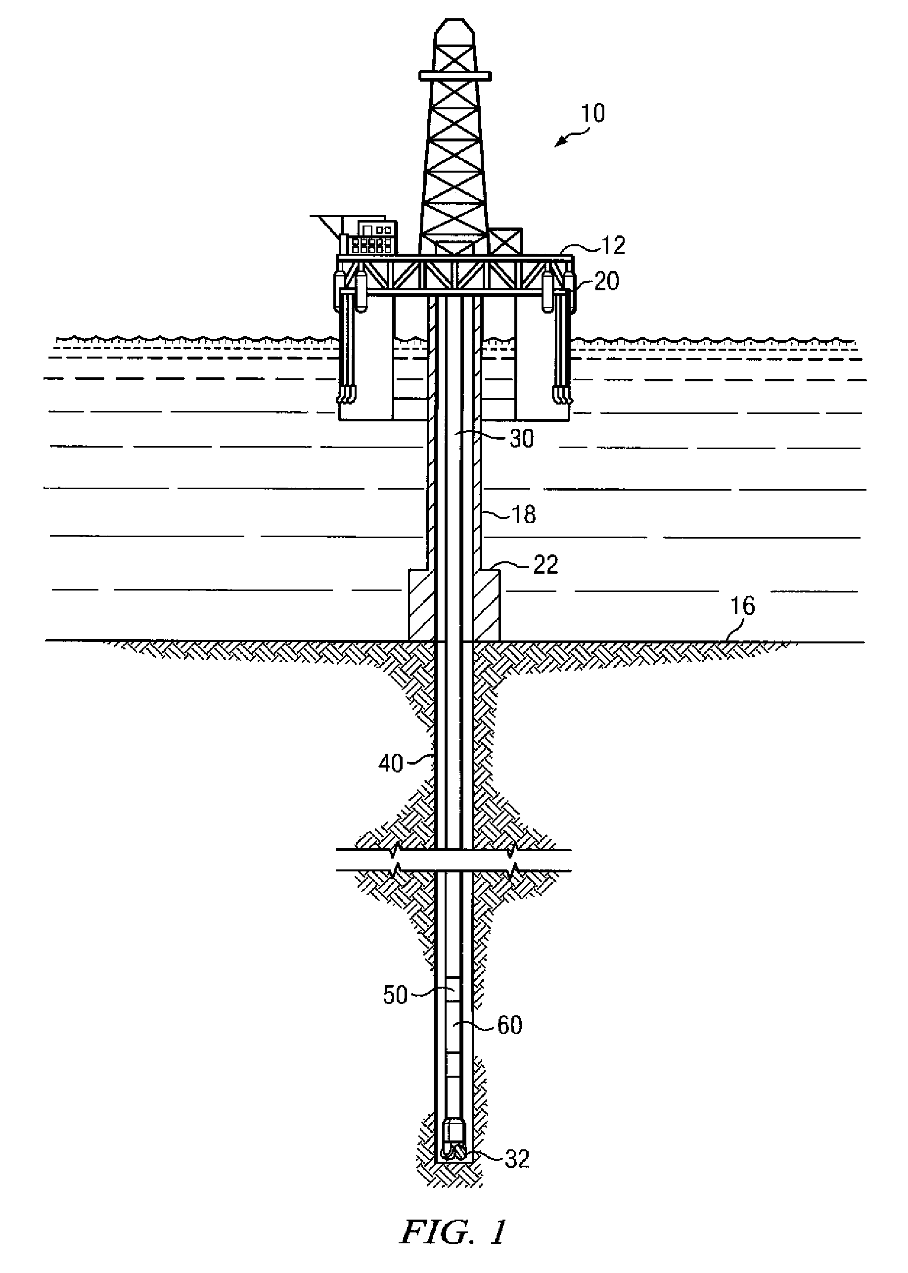
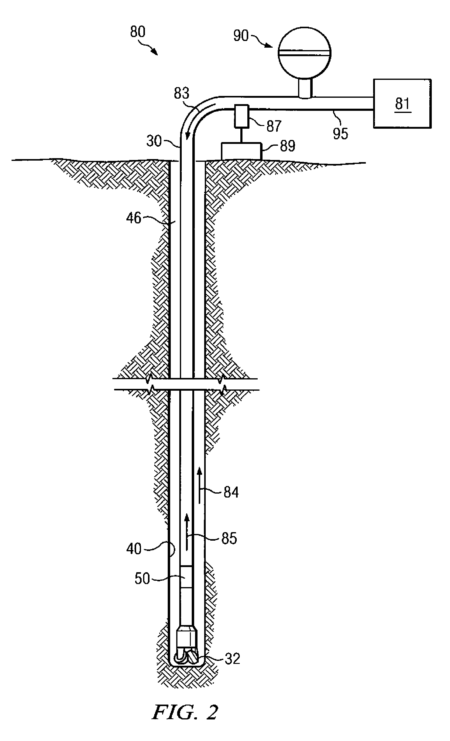
[0022]FIG. 1 depicts an exemplary offshore drilling assembly, generally denoted 10, suitable for employing exemplary method embodiments in accordance with the present invention. In FIG. 1 a semisubmersible drilling platform 12 is positioned over an oil or gas formation (not shown) disposed below the sea floor 16. A subsea conduit 18 extends from deck 20 of platform 12 to a wellhead installation 22. The platform may include a derrick and a hoisting apparatus for raising and lowering the drill string 30, which, as shown, extends into borehole 40 and includes drill bit 32, a transmission device 50 (e.g., a conventional electromechanical pulser), and at least one MWD / LWD tool 60. Drill string 30 may optionally further include substantially any number of other tools including, for example, other MWD / LWD tools, stabilizers, a rotary steerable tool, and a downhole drilling motor.

[0023]It will be understood by those of ordinary skill in the art that the deployment illustrated on FIG. 1 is m...


PUM


Abstract

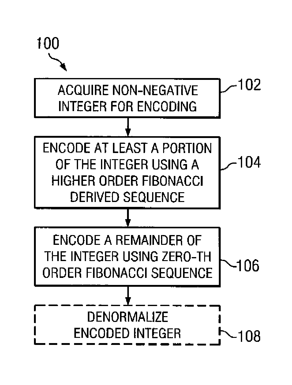
A method for encoding a non-negative integer, for example, representative of MWD / LWD data, includes encoding at least a portion of the integer using at least a first order Fibonacci derived sequence. The remainder of the integer may be encoded using conventional Fibonacci encoding. The invention tends to improve coding efficiency, downhole and surface synchronization, and surface detection.

Description

RELATED APPLICATIONS[0001]None.FIELD OF THE INVENTION[0002]The present invention relates generally to data communication between a downhole tool deployed in a subterranean borehole and surface instrumentation. More particularly, this invention relates to downhole telemetry coding and surface detection and decoding of mud pulse telemetry.BACKGROUND OF THE INVENTION[0003]Typical petroleum drilling operations employ a number of techniques to gather information about the borehole and the formation through which it is drilled. Such techniques are commonly referred to in the art as measurement while drilling (MWD) and logging while drilling (LWD). As used in the art, there is not always a clear distinction between the terms LWD and MWD. Generally speaking MWD typically refers to measurements taken for the purpose of drilling the well (e.g., navigation) and often includes information about the size, shape, and direction of the borehole. LWD typically refers to measurement taken for the pur...

Claims


Application Information

Patent Timeline
Patent Type & Authority Patents(United States)
IPC IPC(8): H03M7/00G01V1/40
CPCE21B47/18H03M7/08H03M7/30G01V1/003
Inventor TANG, CAIMUBEATTIE, MARK S
Owner SCHLUMBERGER TECH CORP
Learn More