
Video encoding method and apparatus, video decoding method and apparatus, programs therefor, and storage media for storing the programs

a video and video image technology, applied in the field of video encoding methods and apparatuses, can solve the problems of difficult to improve the overall encoding efficiency, the encoding efficiency of reference document 2 cannot be improved in comparison with a method using only temporal correlation, and the inability to improve the encoding efficiency of multi-viewpoint video images. , to achieve the effect of improving the encoding efficiency of multi-viewpoint video images

Active Publication Date: 2015-07-21
NIPPON TELEGRAPH & TELEPHONE CORP
View PDF10 Cites 2 Cited by
  • Summary
  • Abstract
  • Description
  • Claims
  • Application Information

AI Technical Summary

Benefits of technology

The present invention provides a new coding technique for multi-viewpoint video images that uses parallactic correlation to improve the efficiency of encoding. This technique can be applied to any type of multi-viewpoint video image that cannot be efficiently encoded using conventional parallactic prediction.

Problems solved by technology

Fixed-length encoding is reversible encoding, however, the encoding efficiency is not good.
In this case, if temporal variation in the subject and background is not so large in the multi-viewpoint video image to be encoded and thus temporal correlation is stronger than parallactic correlation, this method of Reference Document 2 cannot improve the encoding efficiency in comparison with a method using only temporal correlation.
However, in such an easily analogized method, although the encoding efficiency of the quantized value itself of the prediction residual can be improved, the parallax vector for each block should be encoded; thus, it is difficult to improve the overall encoding efficiency.
Also in such an easily analogized method, it is impossible to efficiently encode data to be encoded (e.g., auxiliary data such as coefficients of orthogonal transformation, motion vectors, or macroblock types) other than the prediction residual in the pixel area.

Method used


Image

  • Video encoding method and apparatus, video decoding method and apparatus, programs therefor, and storage media for storing the programs
  • Video encoding method and apparatus, video decoding method and apparatus, programs therefor, and storage media for storing the programs
  • Video encoding method and apparatus, video decoding method and apparatus, programs therefor, and storage media for storing the programs

Examples


Embodiment Construction

[0131]Below, the present invention will be explained in detail in accordance with its embodiments.

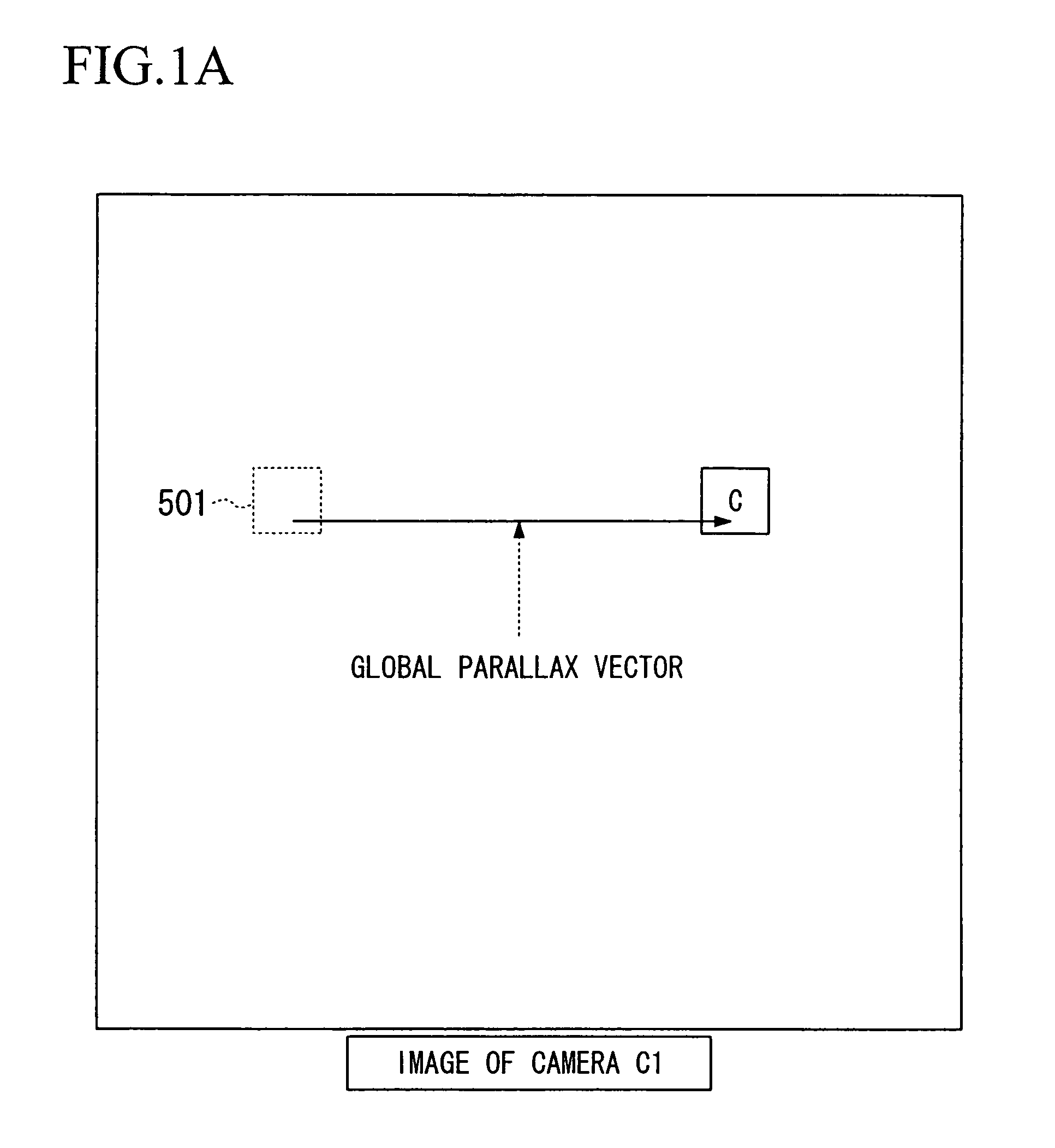
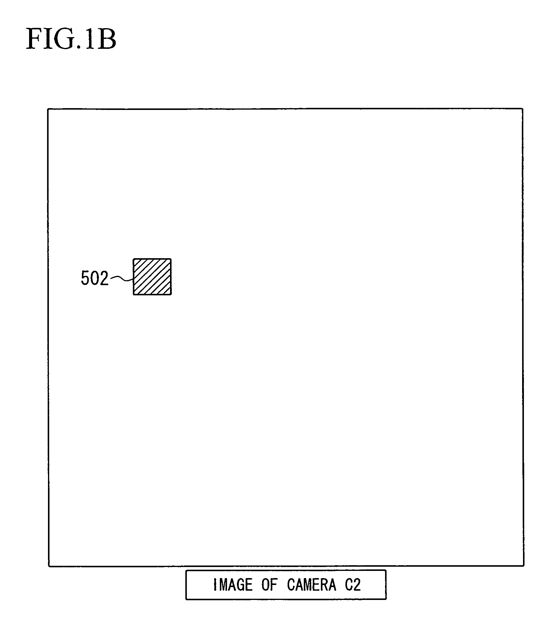
[0132]FIGS. 1A and 1B and FIGS. 2A and 2B show examples of the reference relationship for switching the code table. In these figures, for convenience of explanation, a global parallax vector (i.e., global parallax data) is used as reference parallax data.

[0133]These figures relate to the encoding of images obtained using two cameras (camera C1 and camera C2). Target encoding data with respect to the camera C1 (“target encoding data” indicates all data to be entropy-encoded, that is, a prediction residual, coefficients of orthogonal transformation, macroblock types, or the like) is encoded without referring to the target encoding data for the camera C2, while the target encoding data for the camera C2 is entropy-encoded by referring to the target encoding data of the camera C1, which has already been encoded.

[0134]In the example shown in FIGS. 1A and 1B, the present target encoding data ...


PUM


Abstract

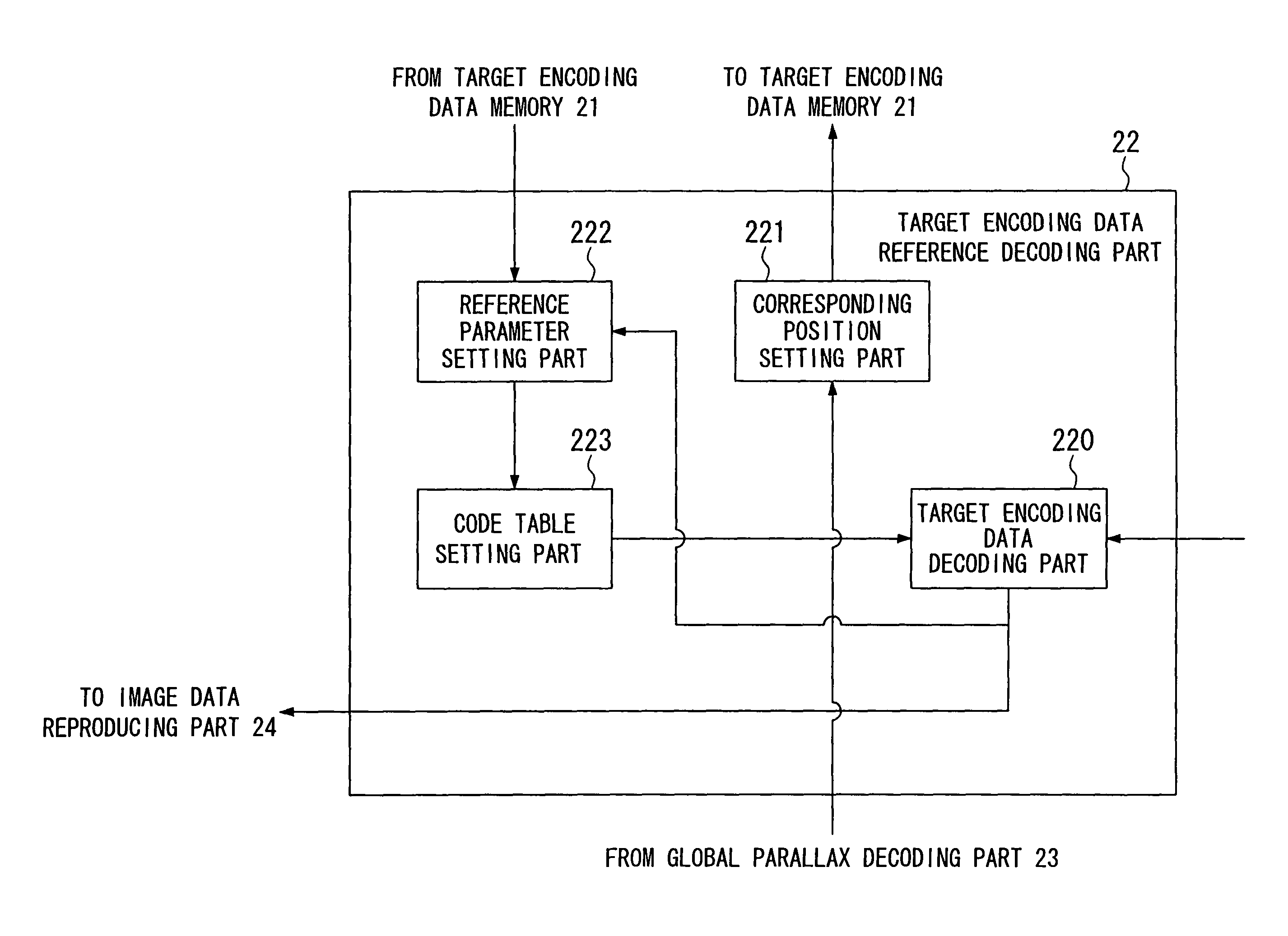
A video encoding method for encoding a plurality of images as a video image. The method includes a reference parallax data setting step of setting reference parallax data which indicates a viewing difference between a first image and an already-encoded second image, in order to encode target encoding data assigned to a predetermined position in the first image; a corresponding position setting step of setting a corresponding position in the second image, which can correspond to the predetermined position, by using the reference parallax data; a code table setting step of setting a code table corresponding to target encoding data assigned to the corresponding position; and a target encoding data encoding step of encoding the target encoding data in the first image by using the code table.

Description

TECHNICAL FIELD[0001]The present invention relates to a video encoding method and a relevant apparatus used for encoding multi-viewpoint video images, a video encoding program for implementing the video encoding method, a computer-readable storage medium which stores this program, a video decoding method and a relevant apparatus for decoding encoded data generated by such a video encoding technique, a video decoding program for implementing the video decoding method, and a computer-readable storage medium which stores this program.[0002]Priority is claimed on Japanese Patent Application No. 2005-002423, filed Jan. 7, 2005, the content of which is incorporated herein by reference.BACKGROUND ART[0003]A multi-viewpoint video image indicates a plurality of video images obtained by a plurality of (video) cameras disposed at different positions, which photograph the same subject and background. Below, a video image obtained by one camera is called a “two-dimensional video image”, and a se...

Claims


Application Information

Patent Timeline
Patent Type & Authority Patents(United States)
IPC IPC(8): H04N7/12H04N11/04H04N19/597H04N19/176H04N19/51H04N19/91H04N19/61H04N11/02H04N19/00H04N13/00H04N13/02H04N13/04H04N19/13H04N19/134H04N19/136H04N19/137H04N19/139H04N19/196H04N19/20H04N19/463H04N19/527H04N19/625H04N19/70
CPCH04N19/91H04N19/176H04N19/51H04N19/597H04N19/61H04N13/00
Inventor KITAHARA, MASAKIKAMIKURA, KAZUTOYASHIMA, YOSHIYUKI
Owner NIPPON TELEGRAPH & TELEPHONE CORP
Learn More