Method for network analyzer calibration and network analyzer

a network analyzer and network analyzer technology, applied in the direction of speed/acceleration/shock measurement, resistance/reactance/impedence, instruments, etc., can solve the problems of difficult preparation of such adapters, difficult to obtain these properties, and insufficient precision of the calibration method of the port extension and the swap equal adapter, so as to achieve simplified equipment operation and fewer measurements

Inactive Publication Date: 2008-01-10
AGILENT TECH INC
View PDF5 Cites 4 Cited by
  • Summary
  • Abstract
  • Description
  • Claims
  • Application Information

AI Technical Summary

Benefits of technology

[0019]By means of the present disclosure, settings relating to an adapter is unnecessary and the equipment operation is simplified when compared to the past. Moreover, the adapter is assembled and disassembled fewer times and there are fewer measurements. Furthermore, by means of the present disclosure, it is not necessary to know the adapter properties prior to calibration.

Problems solved by technology

However, the calibration by the port extension method and the swap equal adapters method is not as precise as by the other methods.
Moreover, the calibration by the swap equal adapters method requires preparation of two types of adapters with very similar properties, but it is difficult to prepare such adapters.
The method whereby a de-embedding function is used requires that the properties of the adapter are known prior to calibration, but there are cases in which it is difficult to obtain these properties.
Calibration by the adapter removal method requires (2xNC2) set full two-port calibration within an N-port measurement environment, and measuring with this frequency becomes a problem.
Moreover, in the case of calibration by the method whereby the adapter is used as the through reference, the calibration procedure becomes more complex with an increase in the number of adapters needed for calibration.
This tends to produce measurement errors.

Method used


Image

  • Method for network analyzer calibration and network analyzer
  • Method for network analyzer calibration and network analyzer
  • Method for network analyzer calibration and network analyzer

Examples


first embodiment

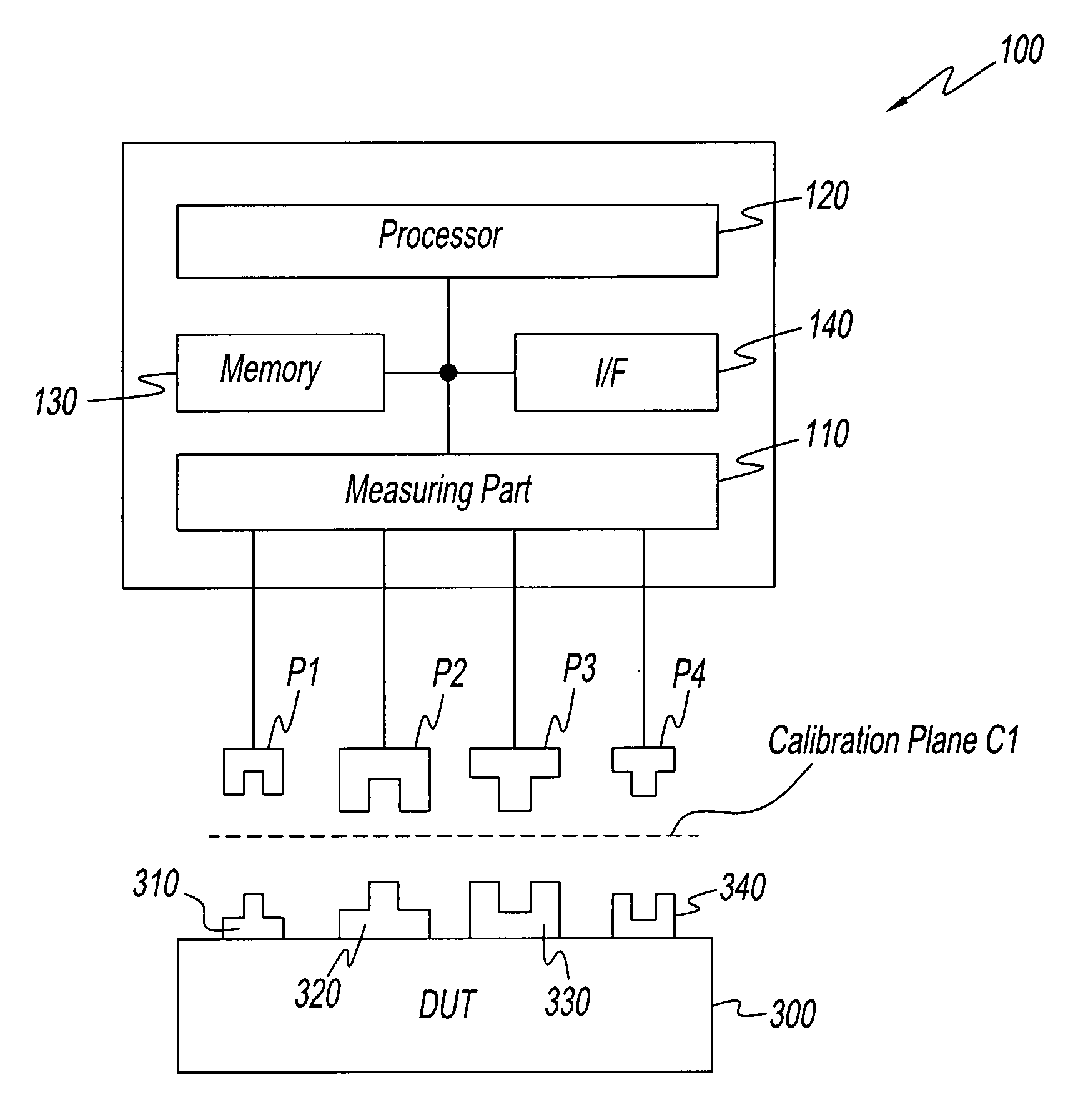
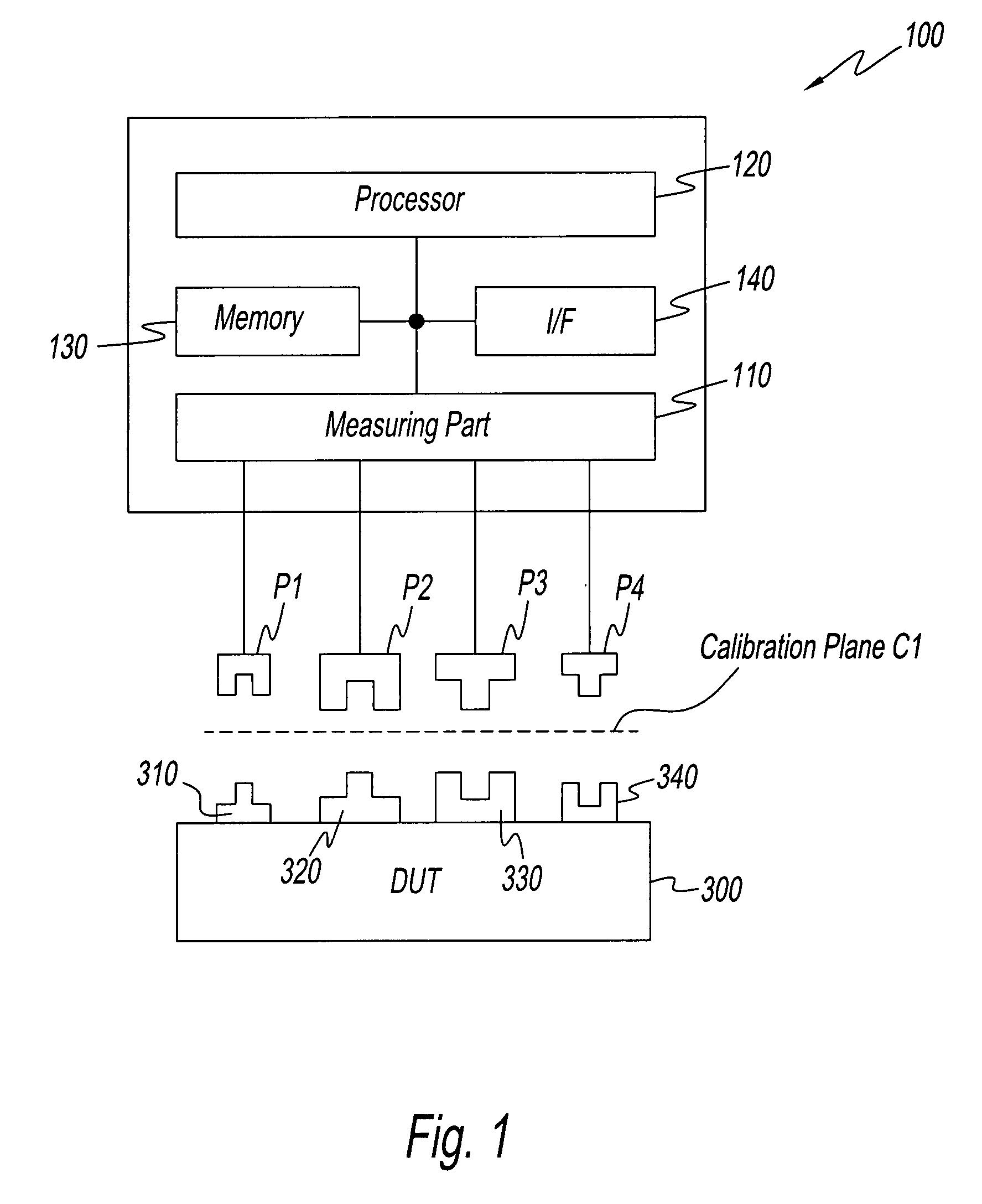
[0031]Embodiments of the present disclosure will be described while referring to the attached drawings. the present disclosure is a network analyzer 100 for measuring circuit parameters such as the S parameter. Refer to FIG. 1. FIG. 1 is a drawing showing the structure of network analyzer 100. Network analyzer 100 comprises a measuring part 110, a processor 120, a memory 130, an interface 140, and test ports P1, P2, P3, and P4. The interface is referred to as the I / F in the following description and drawings. Measuring part 110 is connected to each test port P1, P2, P3, and P4, Although not illustrated, a coaxial cable, adapter, and the like are present between measuring part 110 and test ports P1, P2, P3, and P4. Measuring part 110 can supply measurement signals to any of test ports P1, P2, P3, and P4. Moreover, measuring part 110 can measure outgoing signals and incoming signals at test ports P1, P2, P3, and P4. It should be noted that outgoing signals are signals that are directe...

second embodiment

[0068]Although not shown in the flow chart, the corrected calibration coefficients obtained in step S23 is stored in memory 130 or similar device, and are referred to for error correction during measurement. The preceding is a description of the

[0069]A third embodiment of the present disclosure will now be described. The third embodiment differs from the first embodiment in that the connectors of the test ports are all the same but adapters are used when DUT 300 is measured. The third embodiment is a network analyzer 200 for measuring the circuit parameters, such as the S parameter. Refer to FIG. 10 below. FIG. 10 is a drawing showing the structure of network analyzer 200. The same reference numbers as in FIG. 1 are used for the structural parts in FIG. 10 that are the same as in FIG. 1, and a description thereof has been omitted. Network analyzer 200 comprises measuring part 110, processor 120, memory 130, interface 140, and test ports Q1, Q2, Q3, and Q4. Measuring part 110 is conn...

third embodiment

[0077]When the properties of each adapter for measurement are added to the calibration coefficient, a calibration plane C4 is established between DUT 300 and adapters 460, 470, and 480, as well as test port Q4. Moreover, although not shown in the flow chart, the corrected calibration coefficient obtained in step S33 is stored in memory 130 or similar device, and referred to for error correction during measurement. The preceding is a description of the

[0078]The above-mentioned three embodiments can be modified as follows. First, modification is possible such that in step S12 the properties of the anti-adapter can be found rather than finding the properties of the adapter. In this case, a mathematical operation for finding the properties of the anti-adapter in step S13 is unnecessary. Moreover, the same mathematical operation can be used for correction in the second embodiment and for correction in the third embodiment. This is clear from formulas 7 and 26. Both formulas represent the...


PUM


Abstract

An adapter of unknown properties necessary for performing simple N-port calibration is prepared and simple N-port calibration is performed on a network analyzer using the adapter. Moreover, the open reference, short reference, and load reference are measured in succession, with the adapter in a disassembled state, at the test ports to which the adapter was connected during calibration. Finally, the calibration coefficient obtained by simple N-port calibration is corrected using the properties of the adapter found from the measured values of each reference. N is an integer of two or more.

Description

BACKGROUND[0001]1. Field of the Disclosure[0002]The present disclosure relates to technology for the calibration of a network analyzer. The present disclosure is particularly ideal for network analyzers that measure non-insertable devices.[0003]2. Discussion of the Background Art[0004]When measuring the through connection properties for calibration of a network analyzer, it is usually necessary to directly connect test ports together and bring the through length to zero. When the device under test is an insertable device, a through pass of length zero is obtained by directly connecting the test ports together. The device under test is hereafter referred to as a DUT. On the other hand, when the DUT is a non-insertable device, there is at least one combination of test ports wherein the test ports cannot be directly connected together. Therefore, a method other than the usual method is used to calibrate the network analyzer when the DUT is a non-insertable device. Examples of such cali...

Claims


Application Information

Patent Timeline
Patent Type & Authority Applications(United States)
IPC IPC(8): G01R35/00G01R27/00G06F19/00G01R27/28
CPCG01R35/005G01R27/32
Inventor YAMASAKI, TAKASHI
Owner AGILENT TECH INC
Why Eureka
Try Eureka