
Method, system and computer program for scheduling execution of work units with monitoring of progress thereof

a work unit and work schedule technology, applied in the field of information technology, can solve the problems of affecting the correct execution of the above-described solution, and difficult (if not impossible) to distribute the available resources correctly to the different jobs

Inactive Publication Date: 2008-01-10
IBM CORP
View PDF5 Cites 55 Cited by
  • Summary
  • Abstract
  • Description
  • Claims
  • Application Information

AI Technical Summary

Problems solved by technology

A typical problem of the schedulers is that of ensuring that the jobs are executed when it is required.
Although quite useful, the above-described solution is not completely satisfactory.
Indeed, it is very difficult (if not impossible) to distribute the available resources correctly to the different jobs.
Therefore, it is possible to overcompensate the execution of some jobs so as to complete them even before the corresponding required finish times; moreover, this result might be achieved by withdrawing resources to other jobs, which are then starved with the risk of impairing their correct execution.
All of the above does not allow optimizing the flow of execution of the plan as a whole.
Particularly, the above-mentioned side effects may defeat the advantages provided by the allocation of the additional resources to the late jobs.
This problem is particularly acute for critical jobs, wherein it is of the utmost importance to complete them within the required timeframes.

Method used


Image

  • Method, system and computer program for scheduling execution of work units with monitoring of progress thereof
  • Method, system and computer program for scheduling execution of work units with monitoring of progress thereof
  • Method, system and computer program for scheduling execution of work units with monitoring of progress thereof

Examples


Embodiment Construction

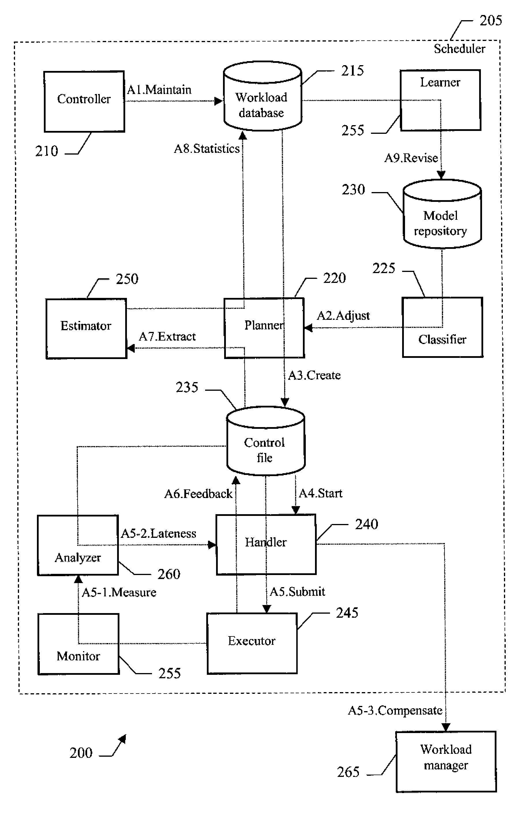
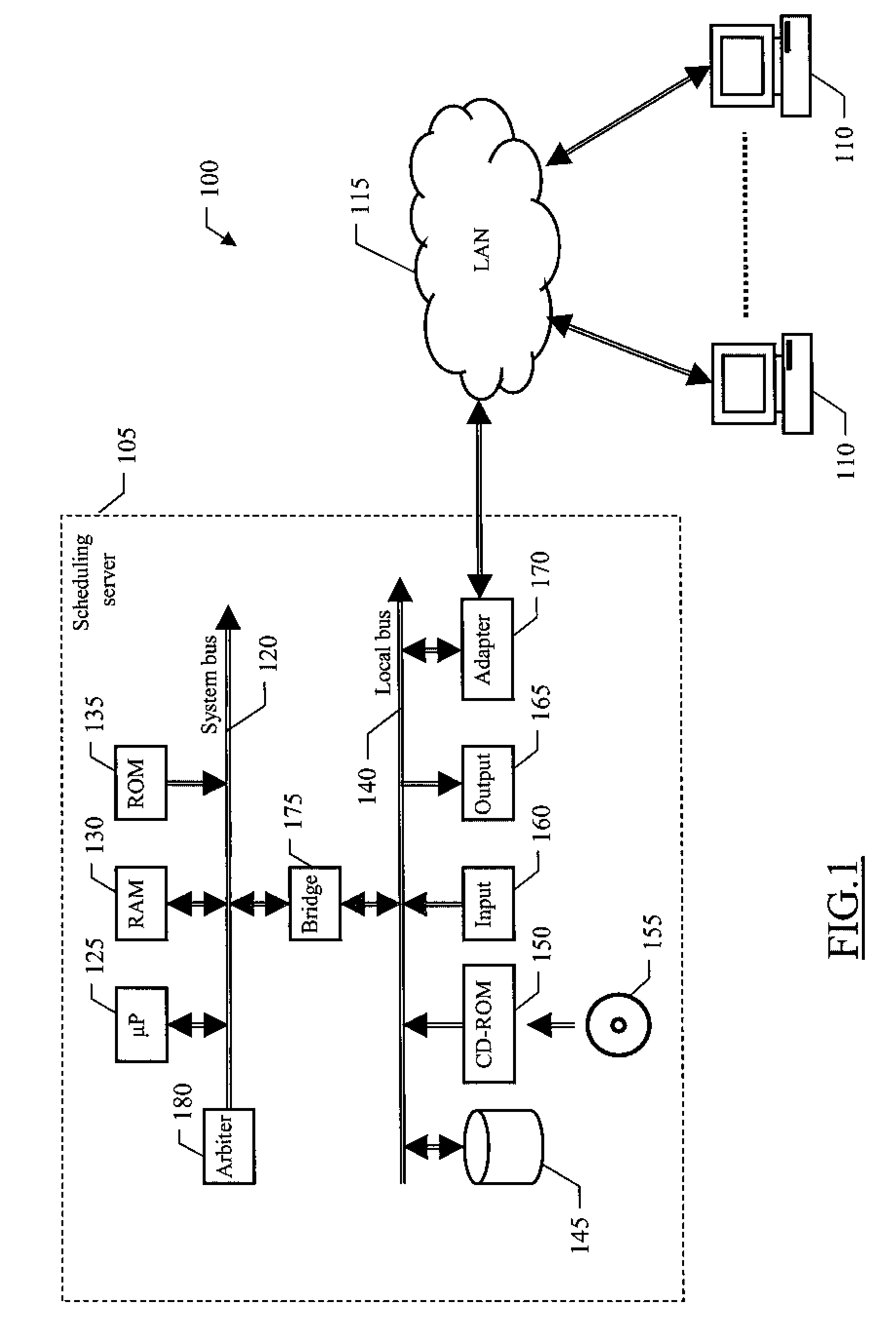
[0028]With reference in particular to FIG. 1, a data processing system 100 with distributed architecture is illustrated. The system 100 includes a central scheduling server 105, which is used to automate, monitor and control the execution of jobs in the system 100. Typically, the jobs consist of non-interactive tasks (for example, relating to accounting applications), which are to be executed on a set of workstations 110. For this purpose, the scheduling server 105 and the workstations 110 communicate through a network 115—such as a Local Area Network (LAN).

[0029]More specifically, the scheduling server 105 is formed by several units that are connected in parallel to a system bus 120. In detail, multiple microprocessors (μP) 125 control operation of the scheduling server 105; a REM 130 is directly used as a working memory by the microprocessors 125, and a ROM 135 stores basic code for a bootstrap of the scheduling server 105. Several peripheral units are clustered around a local bus...


PUM


Abstract

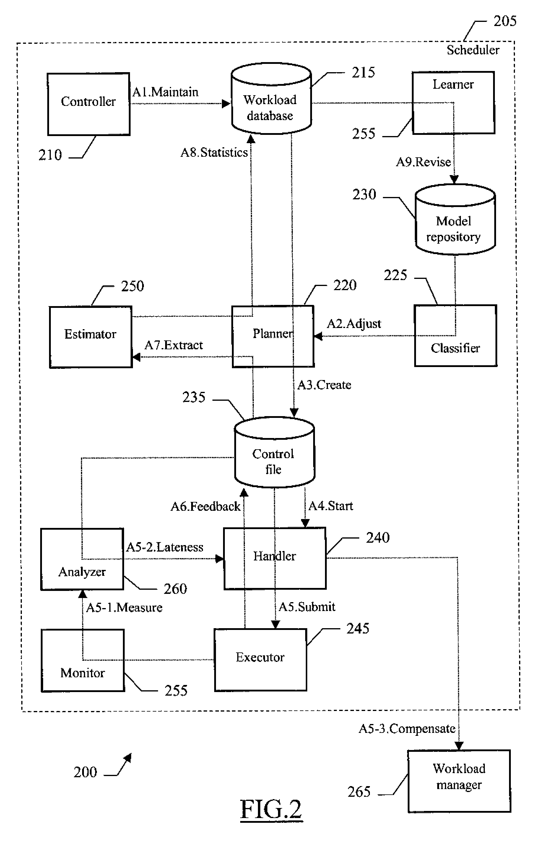
A solution (400) for scheduling execution of jobs is proposed. The submission of the jobs is generally controlled according to a production plan (406), which specifies a required finish time of critical jobs. In the proposed solution, a current progress of each critical job is monitored (427-430)—such as comparing a (measured) number of processor cycles dedicated to the critical job with an estimated total number thereof (required to complete the critical job, as inferred from previous executions thereof). At the same time, an expected progress of each critical job is estimated (433)—such as by the ratio between a time elapsed from an actual start time of the critical job and an allowable duration thereof (from the actual start time to the required finish time). The current progress of each critical job is then compared with its expected progress, so as to identify (436) the critical jobs that are late in their execution. Additional execution resources can then be assigned to each late critical job only when it is necessary to bring back the critical job on schedule.

Description

FIELD OF THE INVENTION[0001]The present invention relates to the information technology field. More specifically, the invention relates to the scheduling of work units in a data processing system.BACKGROUND ART[0002]Scheduling of different work units (for example, batch jobs) is a commonplace activity in data processing systems. For this purpose, workload schedulers have been proposed in the last years to automate the submission of large quantities of jobs from a central point of control; an example of commercial scheduler is the “IBM Tivoli Workload Scheduler (TWS)” by IBM Corporation.[0003]A typical problem of the schedulers is that of ensuring that the jobs are executed when it is required. For this purpose, any scheduler controls the submission of the jobs for their execution according to a specific plan. The plan defines the flow of execution of the jobs in a specific production period (such as one day). The plan is created according to the dependencies of the jobs on the compl...

Claims


Application Information

Patent Timeline
IPC IPC(8): G06F9/46
CPCG06F9/5038G06F2209/5013G06F2209/506G06F2209/508
Inventor MACLELLAN, SCOTORLANDI, IVAN
Owner IBM CORP
Learn More