Camera systems with vibration compensation and methods thereof

a technology of vibration compensation and camera system, applied in the field of camera system, can solve problems such as easy blues and lens collisions

Active Publication Date: 2008-01-17
ASIA OPTICAL INT LTD
View PDF8 Cites 16 Cited by
  • Summary
  • Abstract
  • Description
  • Claims
  • Application Information

AI Technical Summary

Benefits of technology

[0009]An embodiment of a camera system with vibration compensation comprises a first sensor, a second sensor, and a processing module. The first sensor detects an angle variation of a movement of a camera device to generate first sensed data. The second sensor detects a position movement of an image sensor of the camera device to generate second sensed data. The processing module takes the first derivative of the second sensed data, and calculates control information according to the first sensed data and the differential of the second sensed data. The processing module enables a drive device to adjust the position of the image sensor based on the control information.
[0010]In an embodiment of a camera method with vibration compensation, an angle variation of a movement of a camera device is detected by a first sensor to obtain first sensed data. A position movement of an image sensor of the camera device is detected by a second sensor to obtain second sensed data. The first derivative of the second sensed data is taken to obtain the differential thereof. Control information is calculated according to the first sensed data and the differential of the second sensed data, and a drive device is enabled to adjust the position of the image sensor based on the control information.

Problems solved by technology

In handheld use, blurring easily occurs.
However, if significant movement of the compensation lens is required, lenses may collide with each other.

Method used


Image

  • Camera systems with vibration compensation and methods thereof
  • Camera systems with vibration compensation and methods thereof
  • Camera systems with vibration compensation and methods thereof

Examples


Embodiment Construction

[0021]Camera systems and methods with vibration compensation are provided.

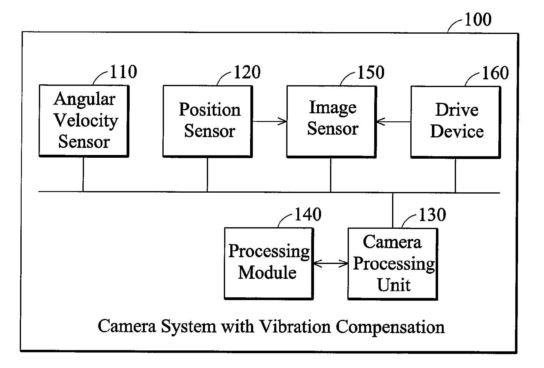
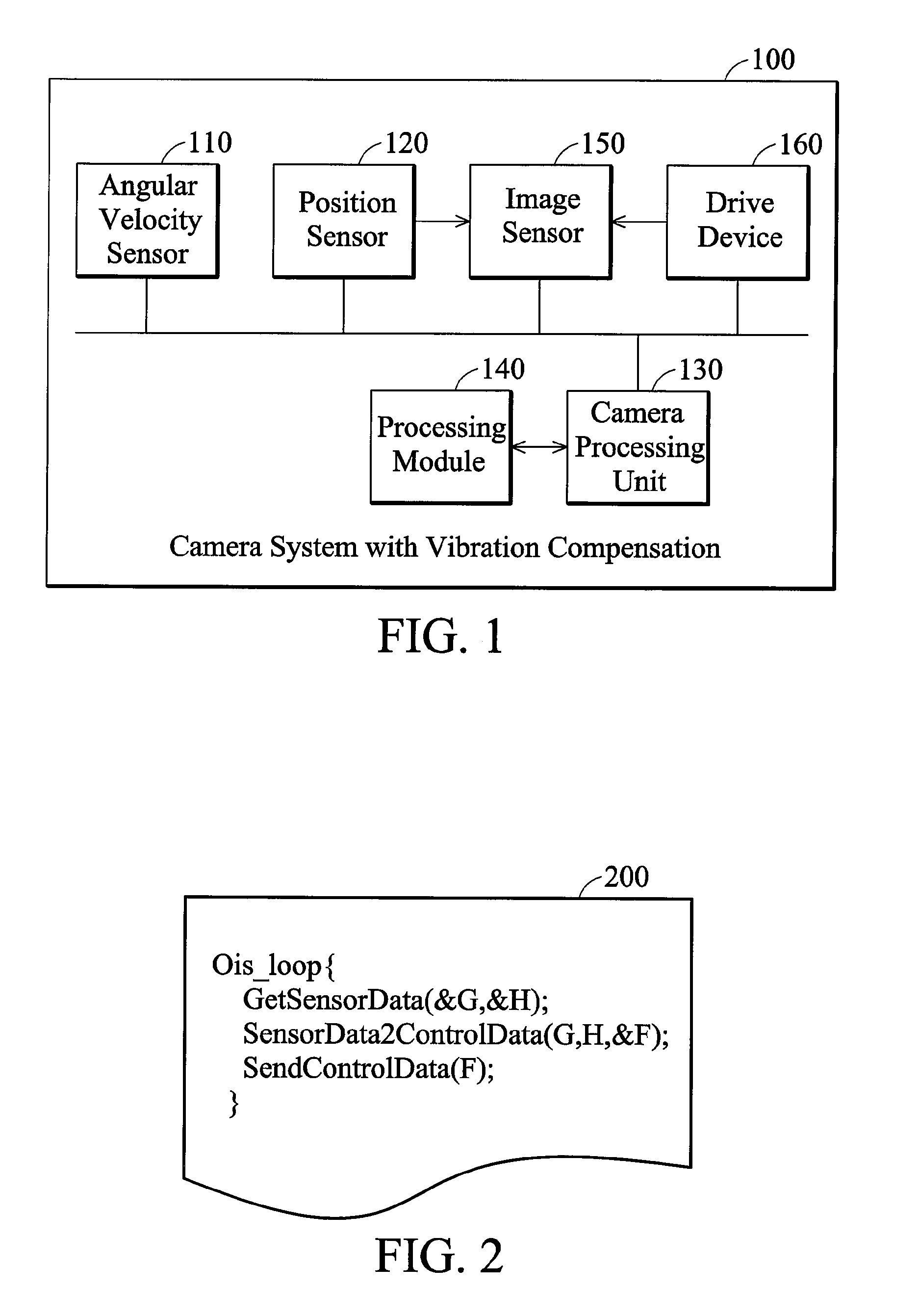
[0022]FIG. 1 is a schematic diagram illustrating an embodiment of a camera system with vibration compensation. The system may be a camera device such as a digital camera. As shown in FIG. 1, the camera system with vibration compensation 100 comprises an angular velocity sensor 110, a position sensor 120, a camera processing unit 130, a processing module 140, an image sensor 150, and a drive device 160.

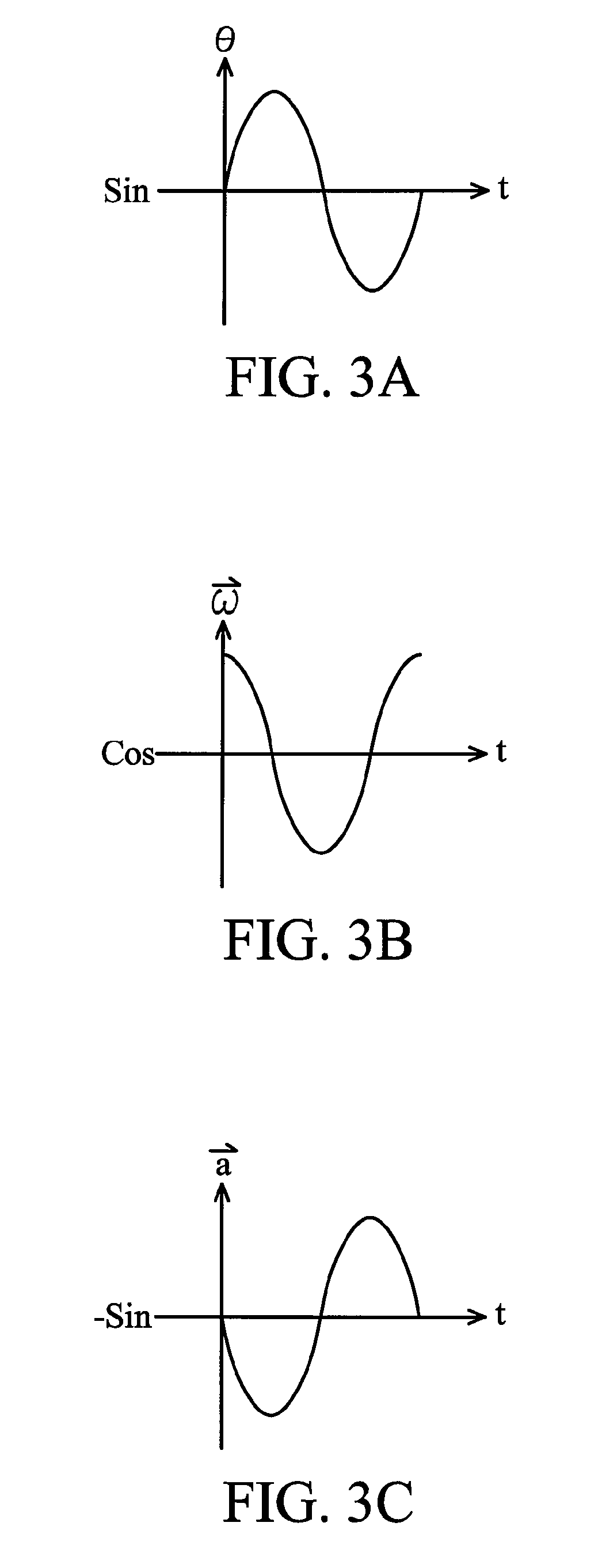
[0023]The angular velocity sensor 110 may be a gyro sensor set in the camera device. The angular velocity sensor 110 detects an angle variation of a movement of the camera device to generate corresponding sensed data. The sensed data of the angular velocity sensor 110 is angular velocity ({right arrow over (ω)}) variation under time (t), as shown in FIG. 3B. The integral of the sensed data of the angular velocity sensor 110 is angular (θ) variation under time (t), as shown in FIG. 3A. The differential of the sens...


PUM


Abstract

Camera systems and methods with vibration compensation. The system comprises a first sensor, a second sensor, and a processing module. The first sensor detects an angle variation of a movement of a camera device to generate first sensed data. The second sensor detects a position movement of an image sensor of the camera device to generate second sensed data. The processing module takes the first derivative of the second sensed data, and calculates control information according to the first sensed data and the differential of the second sensed data. The processing module enables a drive device to adjust the position of the image sensor based on the control information.

Description

BACKGROUND OF THE INVENTION[0001]1. Field of the Invention[0002]The disclosure relates to camera systems and more particularly to systems and methods of vibration compensation.[0003]2. Description of the Related Art[0004]Recently, digital cameras have become commonplace, due to ease of review and processing of captured images in related devices such as computers.[0005]Vibration occurs in all cameras, particularly in digital cameras with light weight and thin volume. In handheld use, blurring easily occurs. Anti-vibration compensation is provided in digital cameras accordingly.[0006]Anti-vibration mechanisms disclosed in U.S. Pat. Nos. 6,332,060 and 5,850,575 employ a position sensor to detect movements of an image sensor. U.S. Pat. No. 6,332,060 detects a vibration velocity of a camera device using a Hall unit, and takes the first derivative of the vibration velocity. U.S. Pat. No. 5,850,575 detects a position movement of a camera device using a Hall unit, and takes the first deriva...

Claims


Application Information

Patent Timeline
Patent Type & Authority Applications(United States)
IPC IPC(8): H04N9/04
CPCH04N5/23248H04N5/23287H04N5/23258H04N23/68H04N23/6812H04N23/687
Inventor LEE, YU-TINGCHIANG, CHIH-YANGCHUNG, LUNG-PIN
Owner ASIA OPTICAL INT LTD
Why Eureka
Try Eureka