

Portable Display Device
- Summary
- Abstract
- Description
- Claims
- Application Information
AI Technical Summary
Benefits of technology
Problems solved by technology
Method used
Image

Examples
Embodiment Construction
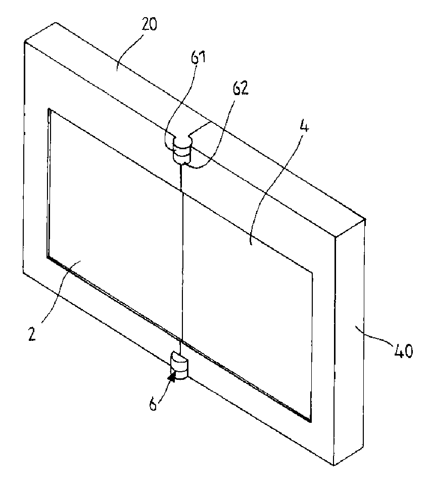
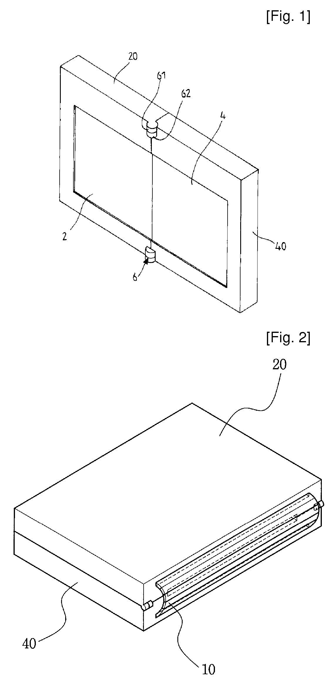
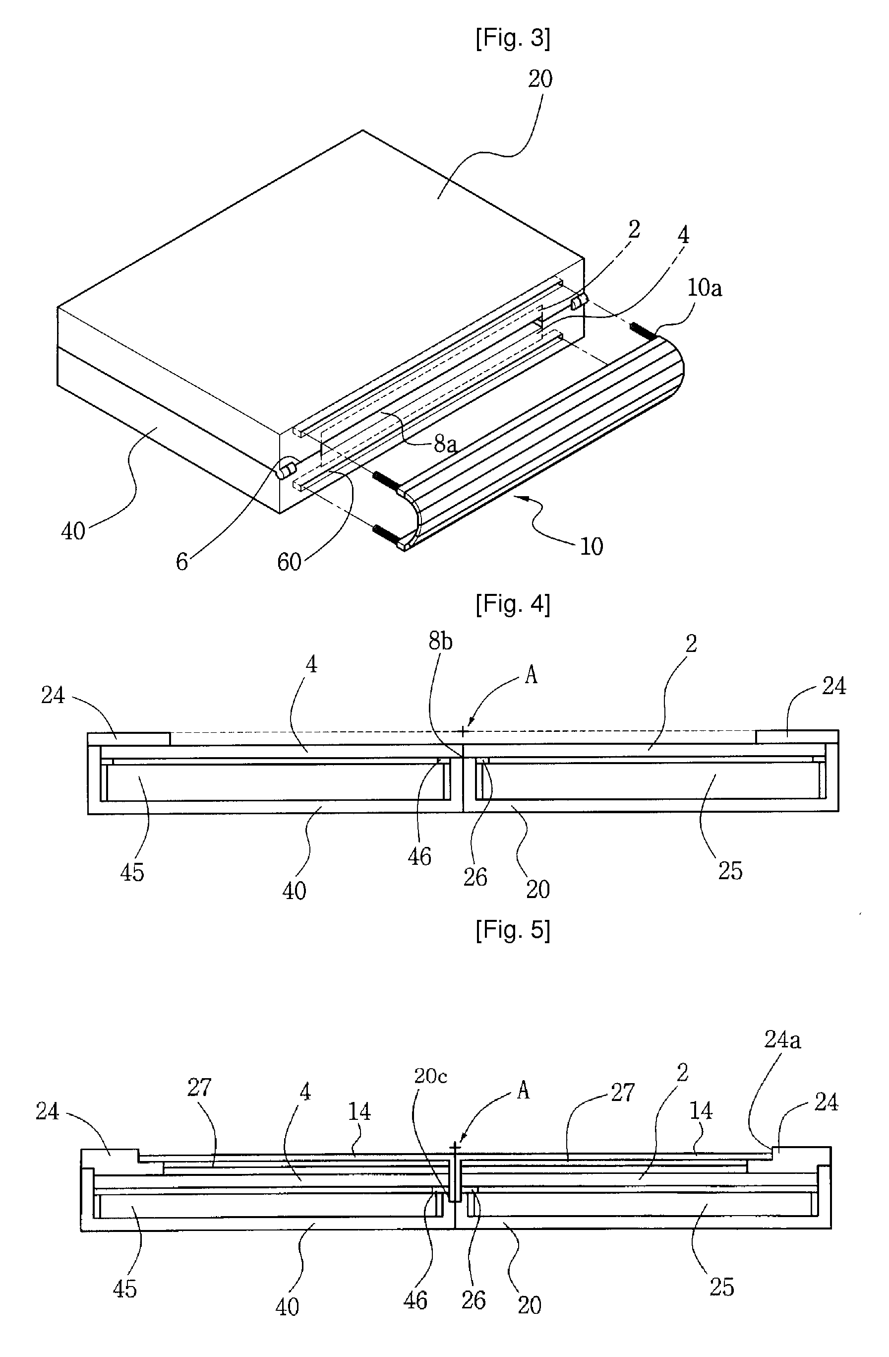
[0042] The present invention provides a foldable type portable display device realizing a large-sized screen by connecting at least two flat display elements. As a display panel, a liquid crystal display (LCD), a thin film transistor (TFT)-LCD, a field emission display (FED), a plasma display panel (PDP), an electro luminescent (EL), an electronic paper and etc., may be used.
[0043] To form a single large screen by adjacently arranging at least two flat display elements, the opposite sidewalls of the display elements should be coming into contact or be positioned within the distance of 4 mm, which means at least two display elements should be arranged enough adjacently to form a single screen.
[0044] According to the present invention, two flat display elements may form a large-sized screen by adjacently arranging the flat display elements.
[0045] FIGS. 1 to 3 show a portable display device according to a first embodiment of the present invention, in which the display device is show...
PUM
 Abstract
Description
Claims
Application Information