Eureka AIR delivers breakthrough ideas for toughest innovation challenges, trusted by R&D personnel around the world.

Selective header field dispatch in a network processing system

a network processing system and header field technology, applied in the field of network processing systems, can solve the problems of increasing packet rate, cumbersome and relatively slow, increasing complexity, etc., and achieve the effect of reducing data throughput capacity and eliminating unnecessary parameter fields

Inactive Publication Date: 2008-01-17
LENOVO GLOBAL TECH INT LTD
View PDF8 Cites 20 Cited by
  • Summary
  • Abstract
  • Description
  • Claims
  • Application Information

AI Technical Summary

Benefits of technology

"The present invention provides a method and structure for efficiently processing data in a network processing system. The invention includes a technique for extracting protocol header fields for use by the network processor. By categorizing packets based on the types of protocol headers present, specific parameter fields are extracted from the corresponding headers and eliminated from the compressed dispatch message, reducing the data throughput capacity required. The invention also combines the compressed dispatch messages from multiple packets into a single composite dispatch message, increasing the network processor's packet forwarding capacity. The network processor uses standard packet forwarding code to process each packet in a composite dispatch message separately, and results from processing each packet are accumulated in a common composite enqueue message to be returned to the data flow device. The invention optimizes performance by overlapping code execution for one packet with memory accesses and table searches for another packet. The data flow device must maintain an identifier for each packet, and the enqueue message is used to control the hardware enqueue operation and required frame alterations."

Problems solved by technology

This becomes more challenging as network links become increasingly fast, with corresponding increases in packet rates.
But this is cumbersome and relatively slow, and network links continue to increase in their transport capacity.

Method used


Image

  • Selective header field dispatch in a network processing system
  • Selective header field dispatch in a network processing system
  • Selective header field dispatch in a network processing system

Examples


Embodiment Construction

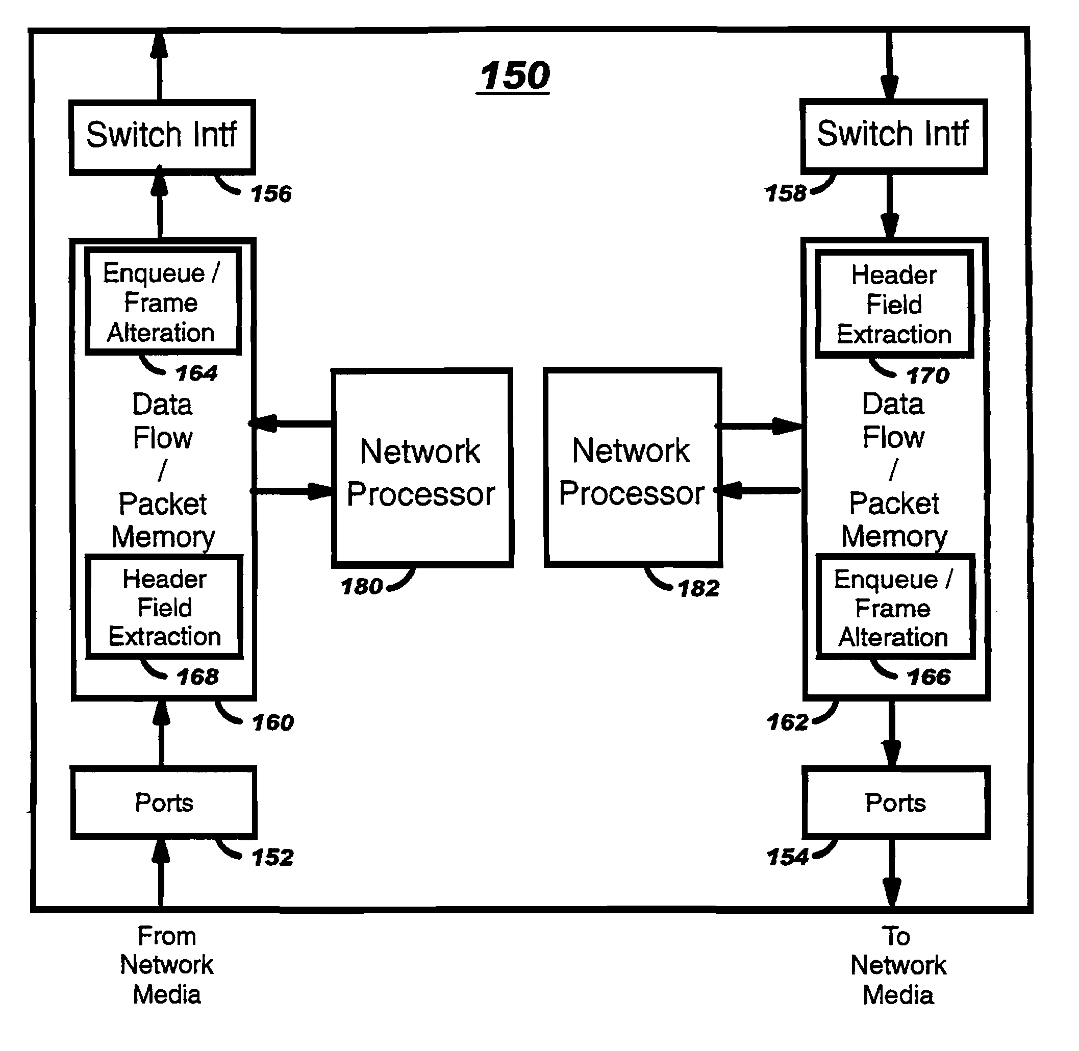
[0038]FIG. 4-A is a depiction of a typical router blade 150 in accordance with the present invention. For very high data throughput such as OC-192 (10 Gigabits per second Packet-over-Sonet), router blade 150 is likely implemented with multiple chips, with ingress data flow 160, egress data flow 162, network processor 180, and network processor 182 each implemented as individual chips. Input ports 152 connect network links into ingress data flow 160, and switch interface 156 connects ingress data flow 160 to a switch fabric (not shown). Likewise, switch interface 158 connects switch fabric (not shown) to egress data flow 162, and output ports 154 connect egress data flow 162 to network links. Within data flow 160, 162 Enqueue / Frame Alteration unit 164, 166 and Header Field Extraction Unit 170, 168 control the flow of data to and from network processors 180, 182, as will be described in more detail below. For blades with lower data throughput such as OC-48 (2.5 Gigabits per second Pac...


PUM


Abstract

A method and structure are disclosed for dispatching appropriate data to a network processing system comprising an improved technique for extracting protocol header fields for use by the network processor. This technique includes basic classification of a packet according to the types of protocol headers present in the packet. Based on the results of the classification, specific parameter fields are extracted from corresponding headers. All such parameter fields from one or more protocol headers in the packet are concatenated into a compressed dispatch message. Multiples of such dispatch messages are bundled into a single composite dispatch message. Thus, selected header fields from N packets are passed to the network processor in a single composite dispatch message, increasing the network processor's packet forwarding capacity by a factor of N. Likewise, multiple enqueue messages are bundled into a single composite enqueue message to direct enqueue and frame alterations to be taken on the bundle of N packets.

Description

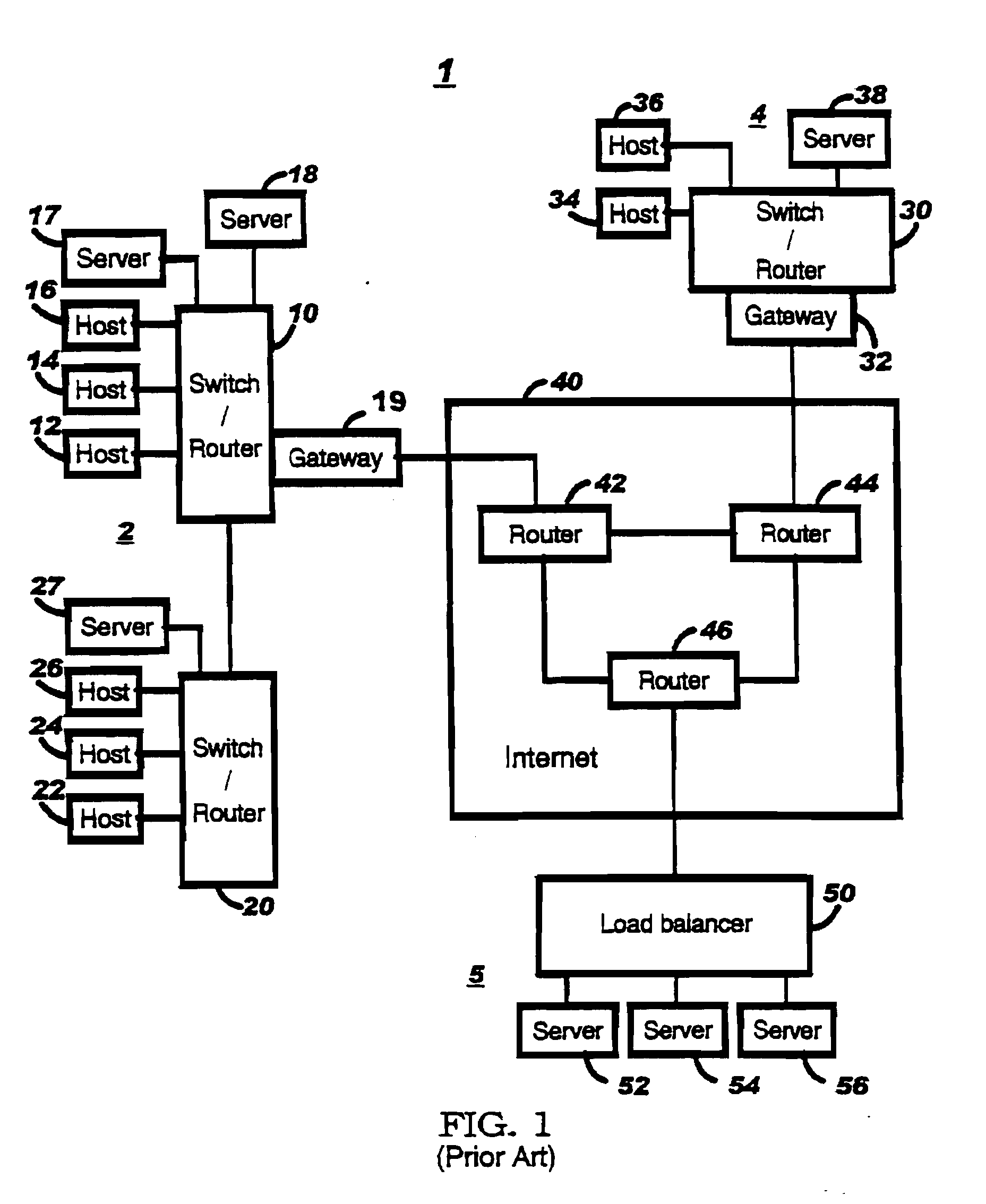
CROSS REFERENCE TO RELATED APPLICATION [0001] This application is a division of application Ser. No. 10 / 170,515, filed Jun. 13, 2002, entitled SELECTIVE HEADER FIELD DISPATCH IN A NETWORK PROCESSING SYSTEM.FIELD OF THE INVENTION [0002] The present invention relates to network processing systems, and more specifically to the dispatching of packet data to a network processor to facilitate the network processor's task of routing, modifying, or otherwise handling associated packets. BACKGROUND OF THE INVENTION [0003] In typical networks, such as those depicted in FIG. 1, switches and routers are used to guide network traffic consisting of packetized data from one node to the next in order to guide each of those packets from its source to its destination. Networking nodes such as switches and routers have previously been implemented using custom logic designs to process these packets. More recently, programmable devices referred to as network processors have been deployed in networking n...

Claims


Application Information

Patent Timeline
Patent Type & Authority Applications(United States)
IPC IPC(8): H04L12/54H04L12/56H04L29/06
CPCH04L49/354H04L69/22H04L49/604H04L49/602
Inventor CALVIGNAC, JEAN LOUISDAVIS, GORDON TAYLOR
Owner LENOVO GLOBAL TECH INT LTD
Why Eureka
Eureka Blog
Learn More