Air bag module for vehicles

a technology for air bags and vehicles, applied in the direction of vehicular safety arrangements, vehicle components, pedestrian/occupant safety arrangements, etc., can solve the problems of difficulty in reducing the time and cost required to install air bags, and achieve the effect of reducing the number of parts required, improving the mounting structure, and reducing time and cos

Inactive Publication Date: 2008-01-24
HYUNDAI MOBIS CO LTD
View PDF22 Cites 17 Cited by
  • Summary
  • Abstract
  • Description
  • Claims
  • Application Information

AI Technical Summary

Benefits of technology

[0009]Therefore, the present invention has been made in view of the above problems, and it is an object of the present invention to provide an air bag module for vehicles, which has an improved mounting structure, so as to reduce the number of parts required to install the air bag module and reduce the time and cost required to install the air bag module.

Problems solved by technology

Further, the above conventional air bag module for vehicles has a complicated mounting structure, thus causing a difficulty in reducing the time and cost required to install the air bag module.

Method used


Image

  • Air bag module for vehicles
  • Air bag module for vehicles
  • Air bag module for vehicles

Examples


first embodiment

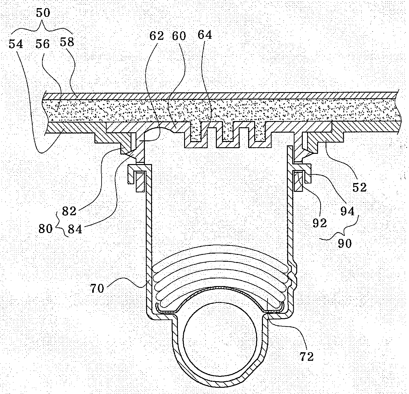
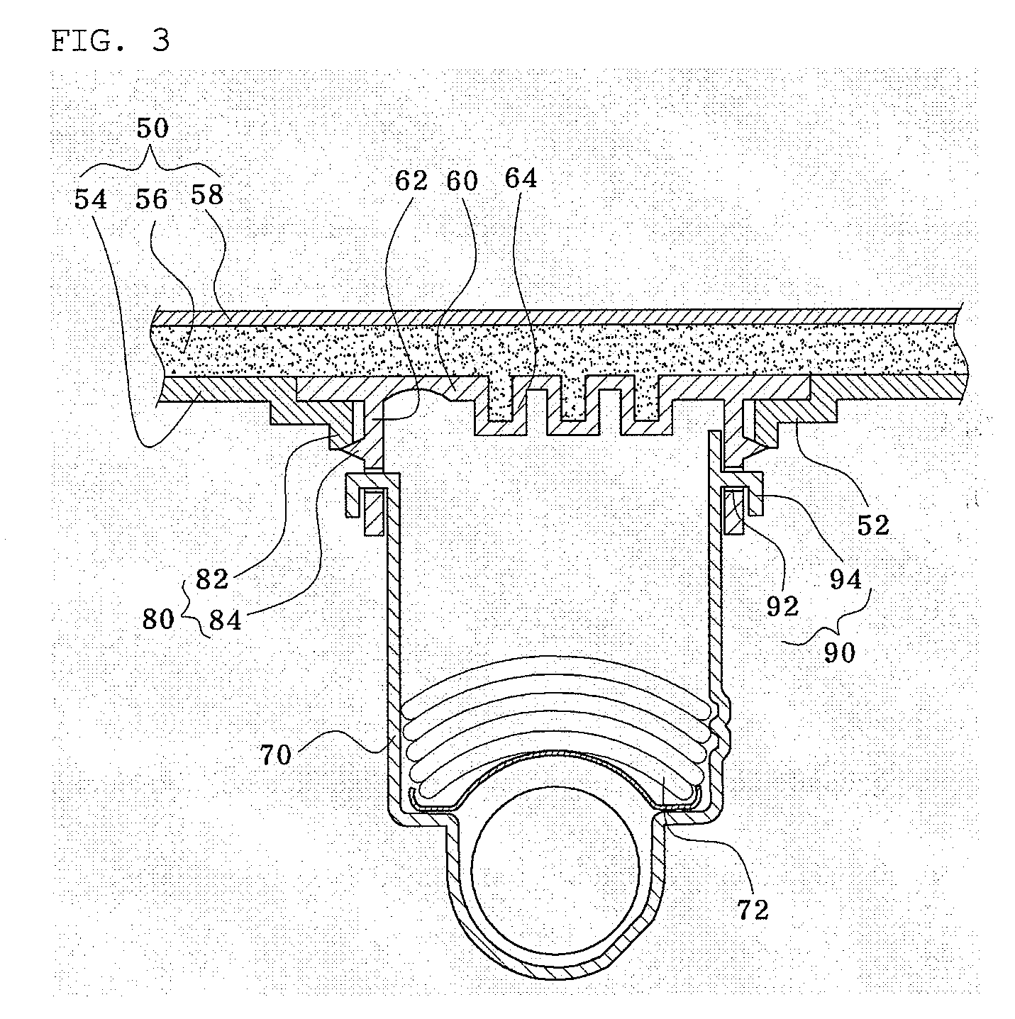
[0038]With reference to FIGS. 3 and 4, an air bag module for vehicles in accordance with the first embodiment includes an instrument panel 50 provided with a receipt hole 52 formed therethrough, an air bag door 60 installed at the receipt hole 52, an air bag housing 70, into which an air bag 72 is put, installed in the receipt hole 52, an extension portion 62 protruded from the air bag door 60 to the inside of the receipt hole 52, a connection unit 90 installed between the extension portion 62 and the air bag housing 70 for connecting the air bag door 60 and the air bag housing 70, and a mounting unit 80 installed between the air bag door 60 and the receipt hole 52 for fastening the air bag door 60 in the receipt hole 52.

[0039]After the air bag housing 70, into which the air bag 72 is put, and the air bag door 60 is connected by the connection unit 90, the air bag door 60 is mounted on the receipt hole 52 formed through an internal panel 54 of the instrument panel 50 by the: mountin...

second embodiment

[0052]The connection unit 190 of the air bag module for vehicles of the second embodiment includes fastening pieces 192 :rotatably installed at the end of the air bag housing 70, coil :springs 196 installed on rotary shafts of the fastening pieces -192, and fastening holes 194 formed through the inner wall of the air bag door 60 corresponding to the fastening pieces 192.

[0053]Here, the fastening pieces 192 have a panel shape inclined to the inside of the air bag housing 70 at a designated angle, and are provided with a curved portion at the ends thereof corresponding to the fastening holes 194.

[0054]When the air bag housing 70 is slid to the fastening holes 194, the curved portions contact the fastening holes 194 and rotate the fastening pieces 192, and the coil springs 196 are compressed. Then, the fastening pieces 192 are rotated to the outside of the air bag housing 70, and reach a state that the air bag housing 70 can be inserted into the air bag door 60.

[0055]Thereafter, when t...

third embodiment

[0057]With reference to FIGS. 7 to 11, an air bag module for vehicles in accordance with the third embodiment is characterized in an air bag door 160.

[0058]The air bag door 160 of the air bag module for vehicles of the third embodiment is provided with fracture holes 108 formed therethrough for tearing the air bag door 160.

[0059]Preferably, the fracture holes 108 are continuously formed and spaced at regular intervals along a C-shaped route.

[0060]Thus, when the air bag 72 is spread, the air bag door 160 is torn off along the fracture holes 108, thereby being opened.

[0061]Particularly, the air bag door 160 is made of plastic, and thus is easily deformed or damaged.

[0062]Therefore, a reinforcing member 110 is formed integrally on the upper or lower surface of the air bag door 160.

[0063]The reinforcing member 110 is made of a metal, and thus reinforces the air bag door 160.

[0064]Preferably, the reinforcing member 110 has a plate shape, and is formed integrally throughout the surface of...


PUM


Abstract

Disclosed is an air bag module for vehicles, which has a simple mounting structure so as to reduce the number of parts, and is easily installed. The air bag module for vehicles includes an instrument panel provided with a receipt hole formed therethrough; an air bag door installed at the receipt hole; an air bag housing, into which an air bag is put, installed in the receipt hole; an extension portion protruded from the air bag door to the inside of the receipt hole; a connection unit installed between the extension portion and the air bag housing for connecting the air bag door and the air bag housing; and a mounting unit installed between the air bag door and the receipt hole for fastening the air bag door in the receipt hole.

Description

BACKGROUND OF THE INVENTION[0001]1. Field of the Invention[0002]The present invention relates to an air bag module for vehicles, and more particularly to an air bag module for vehicles, which has a simple mounting structure so as to reduce the number of parts, and is easily installed.[0003]2. Description of the Related Art[0004]FIG. 1 is a perspective view illustrating the inside of a general vehicle, and FIG. 2 is a longitudinal-sectional view taken along the line A-A of FIG. 1, illustrating a conventional air bag module for vehicles.[0005]With reference to FIGS. 1 and 2, a conventional air bag module for vehicles includes a door 20 installed on an instrument panel 10, an air bag 32 installed in the door 20 and protruded from the outside of the door 20 when a vehicle collision occurs so as to expand in volume, and an air bag housing 30, into which the air bag 32 is put, mounted on the inner surface of the instrument panel 10 and causing the air bag door 20 to be connected thereto.[...

Claims


Application Information

Patent Timeline
Patent Type & Authority Applications(United States)
IPC IPC(8): B60R21/20
CPCB60R21/2165B60R21/205
Inventor YANG, HO JUNSHIN, KWANG SEOB
Owner HYUNDAI MOBIS CO LTD
Why Eureka
Try Eureka