Stern shaft tail tube device for ship and method for mounting stern shaft tail tube device

A stern tube and stern shaft technology, which is applied in the field of marine stern shaft stern tube devices, can solve the problems of high installation work intensity of stern shaft stern tubes, difficulty in disassembling and assembling large-diameter propellers, and fatigue strength of shafting, etc., and achieves a simple and convenient installation structure. and method, the effect of short cycle and high reliability

Active Publication Date: 2017-05-31
YICHANG DONGJIANG SHIPBUILDING CO LTD
View PDF9 Cites 11 Cited by
  • Summary
  • Abstract
  • Description
  • Claims
  • Application Information

AI Technical Summary

Problems solved by technology

[0006] The technical problem to be solved by the present invention is to provide a marine stern tube device, which can solve the problems of high work intensity, long period and high risk in the installation of the stern tube in the prior art. Installation reliability issues, difficulty in disassembly and assembly of large-diameter propellers, and fatigue strength of shafting

Method used


Image

  • Stern shaft tail tube device for ship and method for mounting stern shaft tail tube device
  • Stern shaft tail tube device for ship and method for mounting stern shaft tail tube device
  • Stern shaft tail tube device for ship and method for mounting stern shaft tail tube device

Examples


Embodiment 1

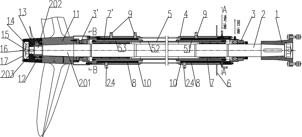
[0040] Head and tail orientation among the present invention are to illustrate attached figure 1 The orientation in the figure 1 The right end is the head end or front end, and the left end is the tail end or back end.

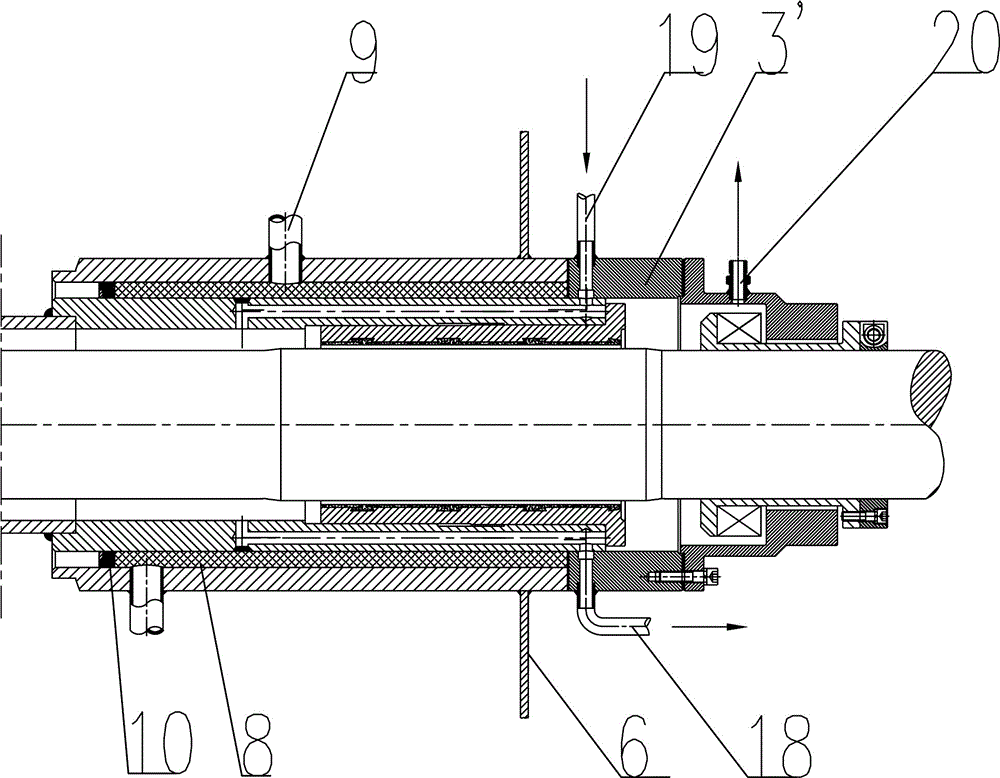
[0041] like Figure 1~6 Among them, a marine stern shaft and stern tube device, the two ends of the stern tube are respectively provided with a head end sealing device 3 and a tail end sealing device 3', wherein the head end sealing device 3 is provided with an oil inlet 19 directly connected to the inner cavity of the stern tube And drain port 18, used to provide lubrication to the bearings. An oil return port 20 is also provided on the head end sealing device 3 . The pipeline distance between the oil inlet 19, the oil discharge port 18 and the oil return port 20 is very short, which is convenient for installation.

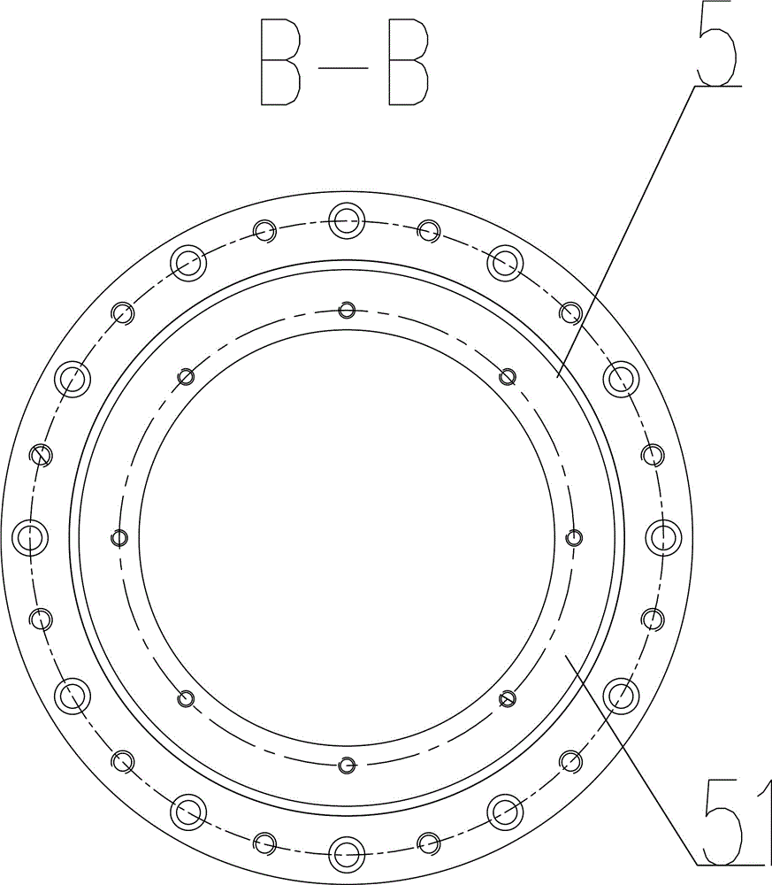
[0042] The structure of the tail pipe is as follows: the outer tail pipe 4 and the inner tail pipe 5 are socketed and connected, the inner t...

Embodiment 2

[0058] The specific manufacturing and installation methods are as follows:

[0059] 1. Workshop manufacturing of inner and outer stern shaft and tail pipes

[0060] 1.1 Outer stern pipe: After rough machining, the qualified front and rear end outer stern pipe steel castings or forged steel parts are assembled and welded together with the middle thick-walled seamless steel pipe. The welding should ensure the concentricity of the two ends of the overall outer stern pipe. The completed integral outer tailpipe is finished in the workshop to meet the design requirements, and it can also be made of integral thick-walled seamless steel pipe.

[0061] 1.2 Inner stern pipe: After rough machining of the qualified head end bearing housing 51 and tail end bearing housing 53, assemble and weld them together with the thick-walled seamless steel pipe connecting pipe 52 in the middle section, and ensure the concentricity of both ends of the overall inner tail pipe during welding. After weldi...


PUM


Abstract

The invention discloses a stern shaft tail tube device for a ship and a method for mounting the stern shaft tail tube device. A head-end sealing device and a tail-end sealing device are respectively arranged at two ends of a tail tube of the stern shaft tail tube device. The stern shaft tail tube device is characterized in that the tail tube is structured in such a manner that an outer tail tube is in sleeve connection with an inner tail tube, the inner wall of the inner tail tube is connected with bearings at two ends of the inner tail tube in an interference fit manner, and a fixing connecting layer is arranged between the outer tail tube and the inner tail tube. The method includes steps of manufacturing the inner tail tube and the outer tail tube in workshops, and carrying out press-fitting on front and rear bearings in place to obtain an inner tail tube assembly; completely mounting the outer tail tube, then mounting the inner tail tube assembly into the outer tail tube from the tail of the outer tail tube and adjusting the inner tail tube until central lines of shaft systems are concentric; pouring the fixing connecting layer. The stern shaft tail tube device for the ship can be mounted by the aid of the steps. The stern shaft tail tube device and the method have the advantages that mounting processes can simplified, the stern shaft tail tube device can be high in positioning accuracy in mounting procedures, and hole boring can be omitted.

Description

technical field [0001] The invention relates to the field of ship propulsion components, in particular to a ship stern shaft stern tube device and an installation method. Background technique [0002] The installation of stern shaft and stern tube of existing ships, especially inland ships, has developed rapidly due to the optimization of the hull line shape, and there have been various ship types such as double tails, double tail fins, external stern tails, vortex tails, and triple tails. The main features are The above-mentioned various stern line types are all very narrow in the position where the stern tube is installed. When the hull shell is installed and welded after the stern tube is installed, it is difficult for the staff to enter its narrow space for welding construction. In this way, the entire stern tube can only It may be installed and welded at both ends, and the stern solid floor between the two ends can hardly be welded with the stern tube, resulting in only...

Claims


Application Information

Patent Timeline
Patent Type & Authority Applications(China)
IPC IPC(8): B63H23/36B63H23/32
CPCB63H23/321B63H23/36B63H2023/327
Inventor 姚智衡王元姚奉
Owner YICHANG DONGJIANG SHIPBUILDING CO LTD
Why Eureka
Try Eureka