Bottom mount refrigerator having an elevating freezer basket

a refrigerator and freezer technology, applied in the field of refrigerators, can solve the problems of affecting the storage of items, and requiring considerable bending on the consumer's behalf, and achieve the effect of facilitating the removal of any items stored

Inactive Publication Date: 2008-01-24
MAYTAG
View PDF21 Cites 95 Cited by
  • Summary
  • Abstract
  • Description
  • Claims
  • Application Information

AI Technical Summary

Benefits of technology

[0009]In accordance with the invention, the refrigerator includes a freezer basket and a second, or upper, slidingly basket supported in the freezer compartment. Actually, the lower freezer basket is operatively connected to the freezer door such that accessing the freezer compartment causes the basket to shift outward. The lower freezer basket is coupled to a lifting mechanism that shifts the lower freezer basket from a first or lowered position to a second or raised position in order to facilitate the removal of any items stored therein. More specifically, if a consumer wishes to access the freezer basket without bending, the lifting mechanism is operated so as to raise the lower freezer basket, preferably to a height corresponding to the upper freezer basket. In accordance with the invention, various mechanisms can be employed to achieve the desired lifting. For example, the lifting mechanism can be formed by a mechanical system such as a linkage system, an electrical system such as a worm screw arrangement, or a pneumatic system which employs a gas assist cylinder.

Problems solved by technology

For instance, in top mount models, accessing lower portions of the fresh food compartment requires considerable bending on behalf of the consumer.
For certain consumers, bending may often times be difficult.
Likewise, in bottom mount models, accessing a lower freezer basket requires a certain amount of bending.
Still, given the size and depth of a freezer basket in a typical bottom mount refrigerator, accessing the freezer basket often times requires significant bending which can outweigh the benefits.

Method used


Image

  • Bottom mount refrigerator having an elevating freezer basket
  • Bottom mount refrigerator having an elevating freezer basket
  • Bottom mount refrigerator having an elevating freezer basket

Examples


first embodiment

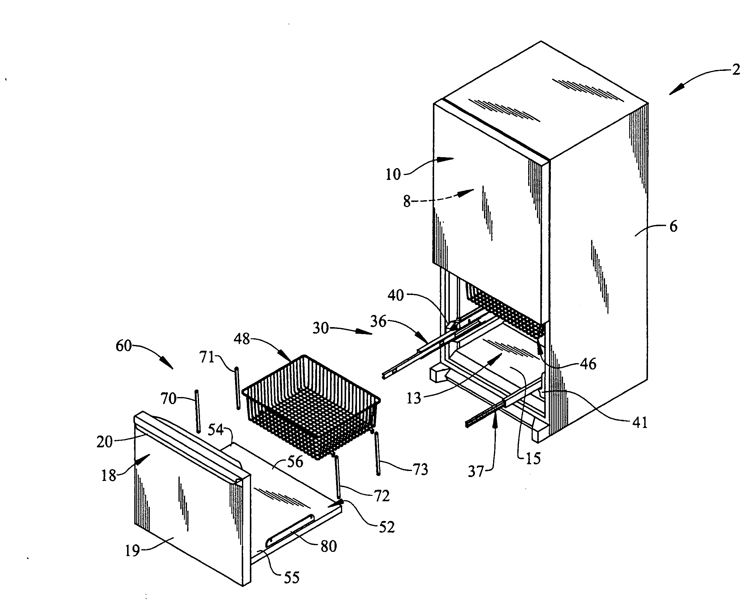
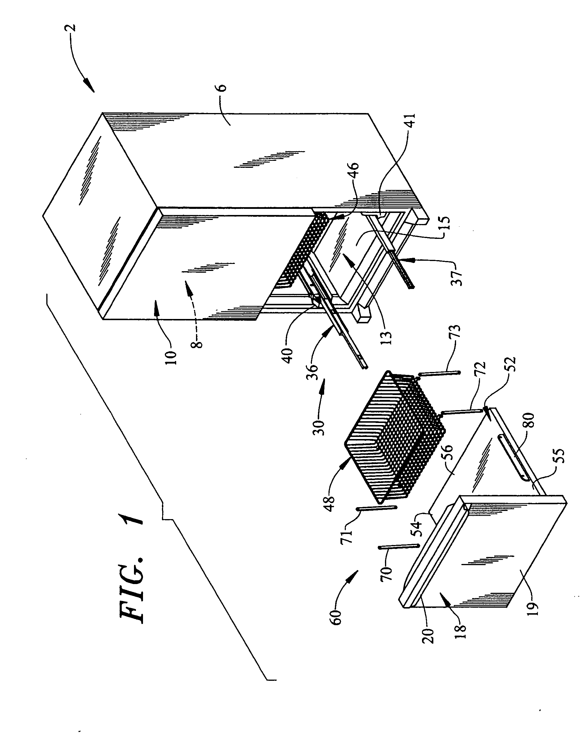
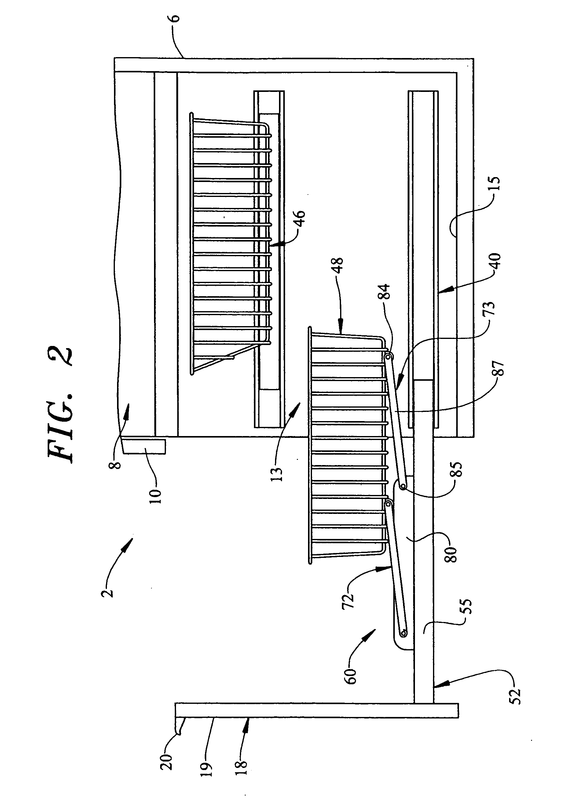
[0020]In accordance with the present invention, lifting mechanism 60 includes a plurality of lifting members 70-73 that are pivotally attached to a pair of base members, one of which is indicated at 80. That is, lifting members 72 and 73 are pivotally secured to base member 80, while lifting members 70 and 71 are secured to a corresponding opposing base member (not shown). Base member 80 and the opposing base member (not shown) are arranged on side portions 54 and 55 of basket support wall 52 with lower basket 48 being arranged therebetween. In any event, as each lifting member 70-73 is constructed similarly, a detailed description will be made with respect to lifting member 73 with an understanding that lifting members 70-72 are substantially identical.

[0021]As best shown in FIGS. 2 and 3, lifting member 73 includes a first end portion 84 that is pivotally connected to basket 48 and that extends to a second end portion 85 through an intermediate portion 87. Second end portion 85 is...

second embodiment

[0023]Reference will now be made to FIGS. 4 and 5 in describing a lifting mechanism 120 constructed in accordance with the present invention. As shown, lifting mechanism 120 includes a plurality of lifting members, two of which are indicated at 130 and 131 shown arranged along side portion 54 of basket support wall 52. In accordance with the embodiment shown, lifting member 130 includes a first end portion 132 which is mounted to basket support wall 52 and extends upward to a second end portion 133 through an intermediate portion 134. Likewise, lifting member 131 includes a first end portion 135 mounted to basket support wall 52 and extends upward to a second end portion 136 through an intermediate portion 137.

[0024]In accordance with the invention, intermediate portions 134 and 137 are threaded so that lifting members 130 and 131 actually constitute part of a worm screw mechanism that will be detailed more fully below. At this point, it should be understood that a second pair of li...

third embodiment

[0027]Reference will now be made to FIGS. 6 and 7 in describing a lifting mechanism 195 constructed in accordance with the present invention. As shown, a pneumatic lifting mechanism 195 includes a lifting member 200 that includes a cylinder portion 210 having a terminal end portion 213. Terminal end portion 213 is pivotally connected to a bracket 214 provided on basket support wall 52. Lifting member 200 also includes a piston or plunger 217 that retractably extends from within cylinder portion 210. Plunger 217 is provided with an end portion 220 that is pivotally connected to a mounting element 225 provided on lower basket 48. Mounting element 225 preferably extends substantially perpendicularly downward from a bottom wall (not separately labeled) of lower basket 48. A second bracket 228 projects from a front wall portion (not separately labeled) of lower basket 48 and includes a guide member 230 in the form of a pin or roller. Guide member 230 transitions within a guide element 23...


PUM


Abstract

A refrigerator includes a cabinet within which is arranged an upper fresh food compartment and a lower freezer compartment. A freezer basket is slidingly supported in the freezer compartment, preferably for concurrent movement with a freezer door. The freezer basket is coupled to a lifting mechanism that selectively shifts the freezer basket from a first or lowered position to a second or raised position in order to facilitate removal of items from the freezer basket. The lifting mechanism can be formed by a mechanical, electrical or pneumatic system.

Description

BACKGROUND OF THE INVENTION[0001]1. Field of the Invention[0002]The present invention pertains to the art of refrigerators and, more particularly, to an elevating freezer basket for a bottom mount refrigerator.[0003]2. Discussion of the Prior Art[0004]There are a number of refrigerator models available for today's consumers. Generally speaking, refrigerators are available in side-by side, top mount and bottom mount models. In side-by-side refrigerator models, fresh food and freezer compartments are arranged laterally adjacent one another. In top mount models, the freezer compartment is arranged above the fresh food compartment. Conversely, in bottom mount models, the freezer compartment is arranged below the fresh food compartment.[0005]In general, top mount and bottom mount models provide more storage options than corresponding side-by-side models. That is, while a side-by-side refrigerator is generally wider then top and bottom mount models, the fresh food and freezer compartments...

Claims


Application Information

Patent Timeline
Patent Type & Authority Applications(United States)
IPC IPC(8): A47B96/04
CPCF25D25/025F25D25/04A47B2210/175A47B2210/04A47B2088/0081A47B2088/901
Inventor CARDEN, MICHAEL SCOTSENNER, KURT C.
Owner MAYTAG
Why Eureka
Try Eureka