
Pulsometer worn on wrist and associated control method

a wristwatch and pulse measurement technology, applied in the field of pulse measurement, can solve the problems of measurement reliability problems, sometimes observed pulse measurement reliability problems, etc., and achieve the effect of increasing the diversity of signals, being economical and simple to implemen

Active Publication Date: 2008-01-24
ETA SA MFG HORLOGERE SUISSE
View PDF7 Cites 14 Cited by
  • Summary
  • Abstract
  • Description
  • Claims
  • Application Information

AI Technical Summary

Benefits of technology

[0008] Owing to the arrangement according to the invention, an increase in the measurement reliability has been observed despite the fact that the receivers are not distributed symmetrically around each light source. In particular, shifting the light source and receiver columns along an orthogonal direction to the direction of the wrist covers a large variety of different physiological characteristics among wearers, which compensates for vascularization differences.
[0015] Advantageously, the electronic circuit includes a unit for calculating a measurement reliability index, which is a function of the pulse values obtained by the pulse calculation unit. This reliability index makes the best use of the diversity of signals generated by the receivers by avoiding displaying unrealistic pulse values and by informing the user as to the quality of the measurements carried out. Moreover, when the reliability index reaches a determined value, the electronic circuit can detect poor positioning of the case on the wrist or a state wherein the pulsometer is not being worn.

Problems solved by technology

Although this arrangement of the diode and the photodiodes generally gives good results, problems of reliability of the pulse measurements are sometimes observed, particularly because of physiological differences between the various wearers, for example as regards the vascularization of the wrist.
These problems of measurement reliability can also appear because of poor positioning of the case on the wrist.

Method used


Image

  • Pulsometer worn on wrist and associated control method
  • Pulsometer worn on wrist and associated control method
  • Pulsometer worn on wrist and associated control method

Examples


case 14

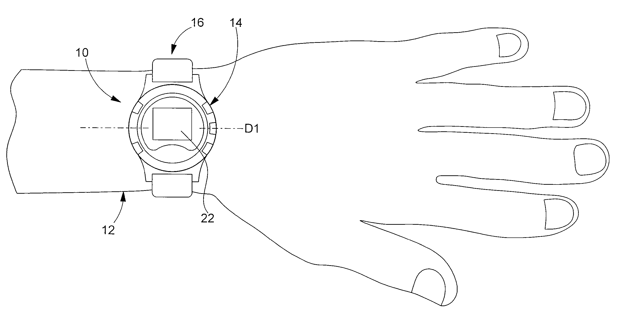
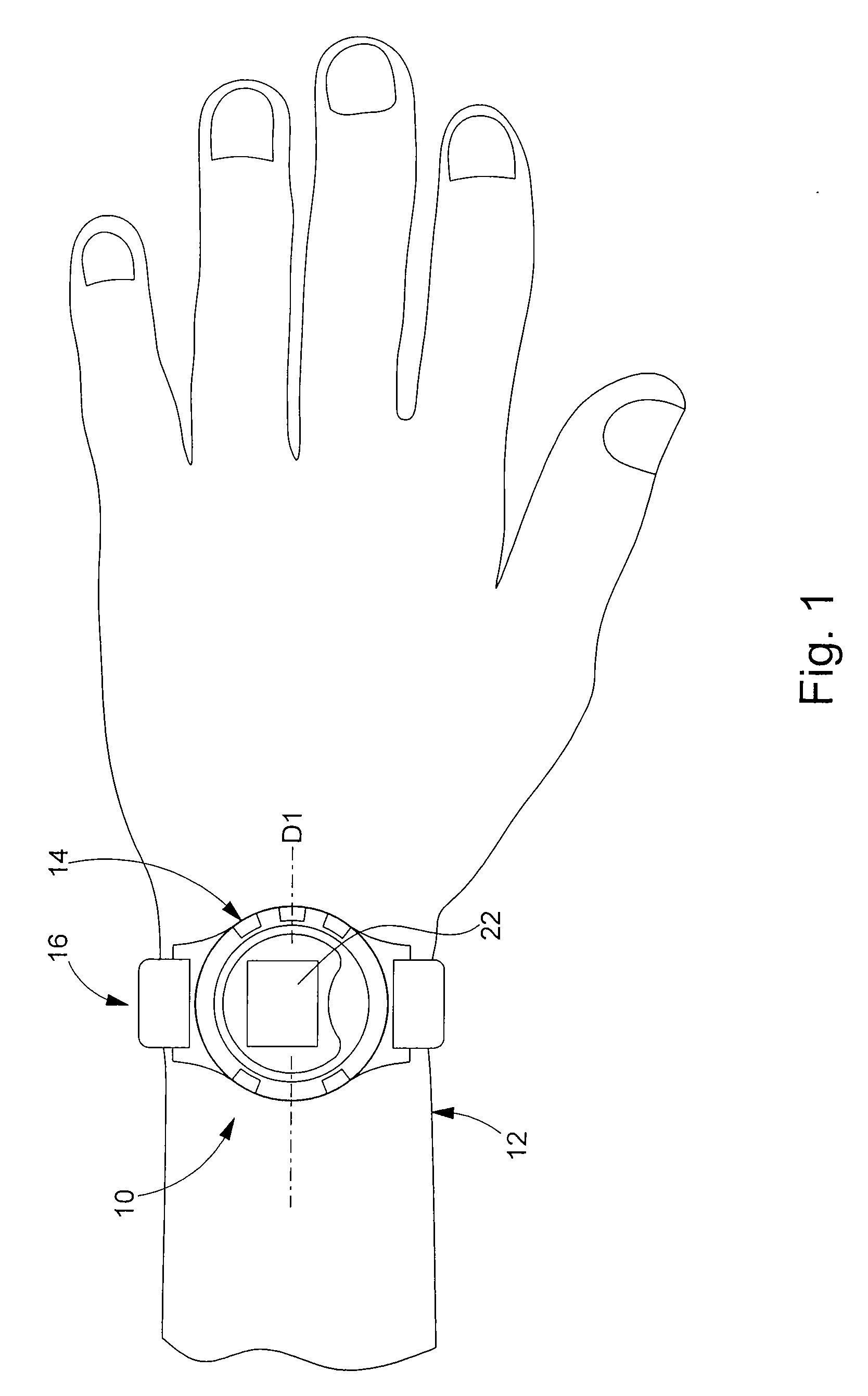
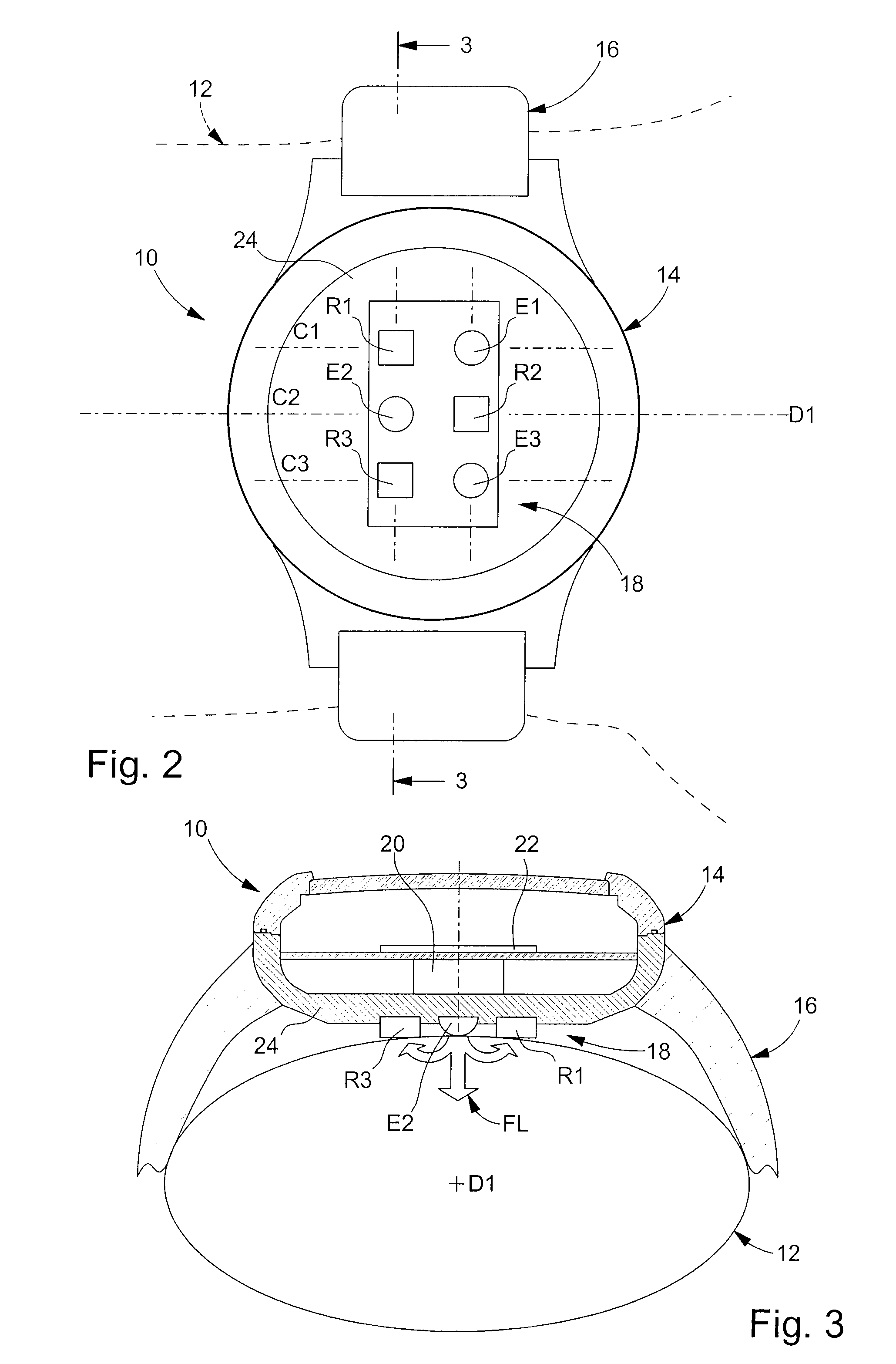
[0027] Case 14 contains an electronic optical device 18 for measuring the wearer's pulse and an electronic circuit 20 for processing measurements in order to calculate and display the wearer's pulse P by means of a display device 22 such as a liquid crystal display.

[0028] The electronic optical measurement device 18 is arranged in the back cover 24 of case 14, on the opposite side to display device 22. Wristband 16 holds back cover 24 of case 14 pressed against wrist 12, so as to optimise the operation of electronic optical measurement device 18.

[0029] In accordance with the teaching of the invention, electronic optical measurement device 18 comprises at least two light sources E1, E2, E3 and at least two light receivers R1, R2, R3, which are oriented towards the wearer's wrist 12 and which are arranged in the form of a matrix including two lines L1, L2 oriented along an orthogonal direction to direction D1 of wrist 12, and at least two columns C1, C2, C3, oriented parallel to the ...


PUM


Abstract

The invention proposes a pulsometer (10) comprising a case (14) which contains an electronic optical pulse measuring device (18) and an electronic circuit, a tightening wristband (16) which holds the back cover of the case (14) pressed against the wrist (12), characterized in that the electronic optical measuring device (18) includes at least two light sources (E1, E2, E3) and at least two receivers (R1, R2, R3), in that the light sources (E1, E2, E3) and the receivers (R1, R2, R3) are arranged in the form of a matrix comprising two lines (L1, L2) each oriented along an orthogonal direction to the direction (D1) of the wrist (12), and at least two columns (C1, C2, C3), oriented parallel to the direction (D1) of the wrist (12), in that each line (L1, L2) of the matrix alternately contains a light source (E1, E2, E3) and a receiver (R1, R2, R3), and each column (C1, C2, C3) of the matrix contains a light source (E1, E2, E3) and a receiver (R1, R2, R3). The invention also proposes a control method for this pulsometer (10).

Description

[0001] This application claims priority from European Patent Application No. 06117653, filed Jul. 21, 2006, the entire disclosure of which is incorporated herein by reference. FIELD OF THE INVENTION [0002] The present invention concerns a pulsometer that can be worn on the wrist and a control method for the same. [0003] The invention concerns more specifically, a pulsometer worn on the wrist comprising a case that contains an electronic optical device for measuring the pulse of the person wearing the pulsometer and an electronic circuit for processing the measurements in order to calculate the pulse, a tightening wristband which holds the back cover of the case pressed against the wrist, wherein the electronic optical measuring device comprises at least one light source and several light receivers, which are arranged in the back cover of the case and which are oriented towards the wrist. BACKGROUND OF THE INVENTION [0004] This type of pulsometer is disclosed in particular in US Pate...

Claims


Application Information

Patent Timeline
Patent Type & Authority Applications(United States)
IPC IPC(8): G04C17/00
CPCA61B5/02416A61B5/0245A61B5/02438A61B5/02
Inventor KLOPFENSTEIN, FRANCOISVETTER, ROLFRENEVEY, PHILIPPENEUMAN, VICTORVERJUS, CHRISTOPHE
Owner ETA SA MFG HORLOGERE SUISSE
Learn More