
Position Detecting Sensor

a position detecting and sensor technology, applied in the direction of electrical/magnetic measurement arrangements, structural/machine measurement, machine parts testing, etc., can solve the problems of lowering the durability of the sensor, excessive force applied to the housing, and increasing the load applied to so as to improve the durability of the position detecting sensor, improve the reliability and stability, improve the effect of the detection accuracy

Active Publication Date: 2008-01-31
SMC CORP
View PDF3 Cites 21 Cited by
  • Summary
  • Abstract
  • Description
  • Claims
  • Application Information

AI Technical Summary

Benefits of technology

[0008]A general object of the present invention is to provide a position detecting sensor, which can be reliably and stably fixed with respect to an actuator, and further, wherein detection accuracy by the detector can be improved, together with improving durability of the position detecting sensor.

Problems solved by technology

Further, when the position detecting sensor is fixed, the housing is pressed at an excessive force against the inner wall surface of the installation groove.
Therefore, when the housing is formed from a resin material, there is a concern that the load applied to the position detecting sensor increases and durability of the sensor is lowered.

Method used


Image

  • Position Detecting Sensor
  • Position Detecting Sensor
  • Position Detecting Sensor

Examples


Embodiment Construction

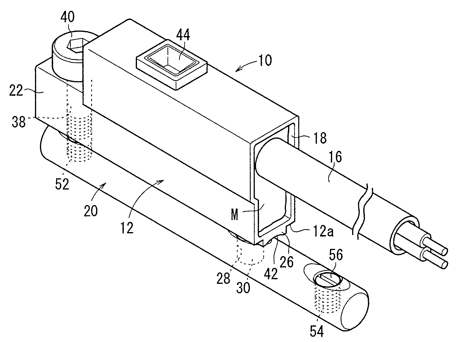
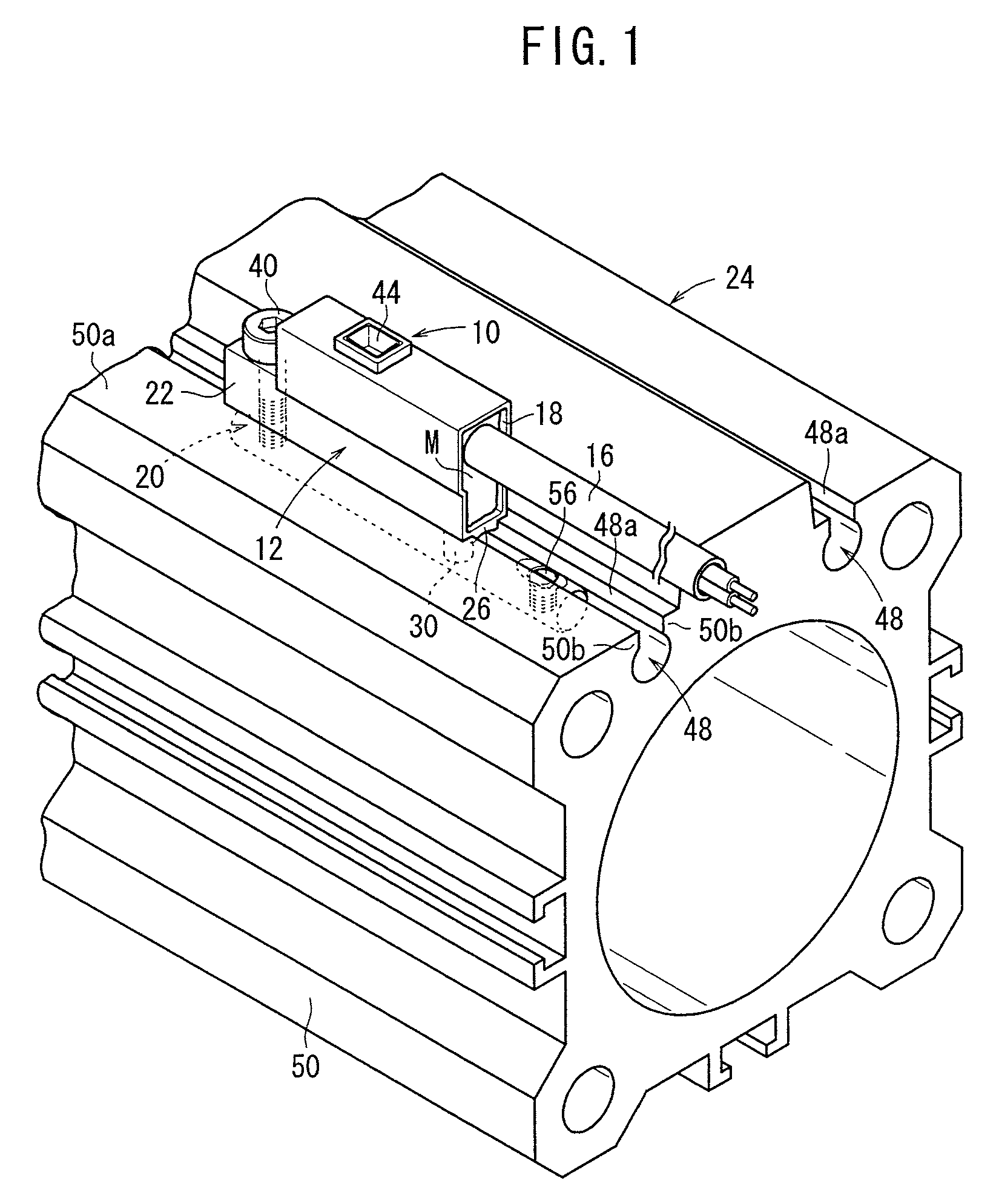
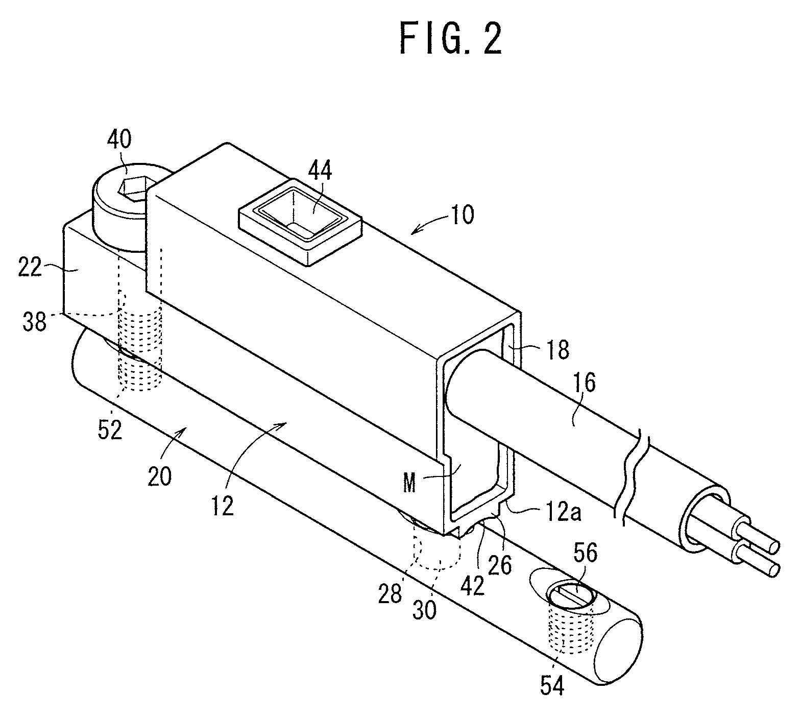
[0032]The position detecting sensor 10, as shown in FIGS. 1 to 6, includes a hollow holder 12 formed from a resin material, a sensor 14 inserted into the holder 12, and lead wires 16 connected to an end of the sensor 14.

[0033]The holder 12 is approximately rectangular in cross section having a bottomed tubular shape, and includes an opening 18 disposed on one end thereof into which a sensor 14 is inserted, a connector 22 disposed on the other end and connected with respect to a fitting 20, to be described later, an engaging projection 26 that projects from a bottom side surface 12a for engagement with one side of a cylinder apparatus (actuator) 24, and a pin (engagement member) 30 disposed on the bottom side surface 12a, which engages in a pin hole 28 of the fitting 20.

[0034]The opening 18 is roughly rectangular in cross section, wherein the sensor 14, with lead wires 16 connected thereto, is inserted through the opening 18 (see FIG. 6) into the holder 12. Also, a molten resin mater...


PUM


Abstract

A position detecting sensor is equipped with a holder capable of accommodating a sensor member therein on which a magnetic sensor is disposed. A connector formed on an end of the holder is connected to a fitting through a connecting bolt. The fitting is disposed by insertion into a sensor groove of a cylinder apparatus, and after insertion of the fitting into the sensor groove, the holder and the fitting are fastened by the connecting bolt, thereby fixing the holder with respect to the cylinder apparatus.

Description

BACKGROUND OF THE INVENTION[0001]1. Field of the Invention[0002]The present invention relates to a position detecting sensor for application, for example, to an actuator or the like and which is capable of detecting a displacement amount.[0003]2. Description of the Related Art[0004]Heretofore, a position detecting sensor has been used for detecting a displacement position of a piston in an actuator or the like. The position detecting sensor, for example, is installed in an installation groove formed along an outer side surface of the actuator, and is equipped with a housing that is inserted into the installation groove, a detector disposed inside the housing, which is capable of detecting displacement of the piston, and a screw that is threaded into an end of the housing. The position detecting sensor is arranged in a movable manner along the installation groove via the housing.[0005]More specifically, after the position detecting sensor is moved to a desired position along the inst...

Claims


Application Information

Patent Timeline
Patent Type & Authority Applications(United States)
IPC IPC(8): G01B7/00
CPCF15B15/2892G01B7/012G01D11/30G01M13/00
Inventor OKUNO, HARUHIKOOZAKI, NORIMASAUCHIMIDO, GENKOBAYASHI, KATSUMI
Owner SMC CORP
Learn More