Flexible downspout connector apparatus

a connector and flexible technology, applied in mechanical devices, roof drainage, couplings, etc., can solve the problems of reducing the service life of the connector, the dimensions of both elements that are connected together do not allow for variations in dimensions, and the rear end of the tubular hinge assembly. , to achieve the effect of low manufacturing cost, convenient and efficient manufacturing and marketing, and durable and reliable construction

Active Publication Date: 2008-01-31
TAT ONE SOURCE LLC
View PDF15 Cites 45 Cited by
  • Summary
  • Abstract
  • Description
  • Claims
  • Application Information

AI Technical Summary

Benefits of technology

[0020] To achieve the foregoing and other advantages, the present invention, briefly described, comprises a flexible downspout connector apparatus including a flexible extension pipe, a first adapter member and a second adapter member, both nested together at one end of the pipe. The first adapter member includes a connection portion for connecting to a downspout outlet end of a first size, and the second adapter member includes a connection portion for connecting to a downspout outlet of a second size. The second adapter member is releasably telescoped with respect to the second adapter member and may be left in place or easily removed at the option of the user to accommodate for different downspout outlet end sizes.

Problems solved by technology

Such a flaccid, collapsible device is subject to cuts and tears.
The fixed dimensions of both elements that are connected together do not allow for variations in the dimensions of either the hose pipe connector or the fitting on the fluid container.
The front and rear ends of the tubular hinge assembly have fixed dimensions and are not adapted to connect to structures that have different fixed dimensions.
Yet, another problem often arises in connecting a downspout to a drainage extension.
Although the drainage extension has a connection of proper cross-section to connect with a downspout having a similar cross-section, the dimensions of the connector on the drainage extension do not match the dimensions of the connector on the downspout.
This patent does not address this problem.

Method used


Image

  • Flexible downspout connector apparatus
  • Flexible downspout connector apparatus
  • Flexible downspout connector apparatus

Examples


Embodiment Construction

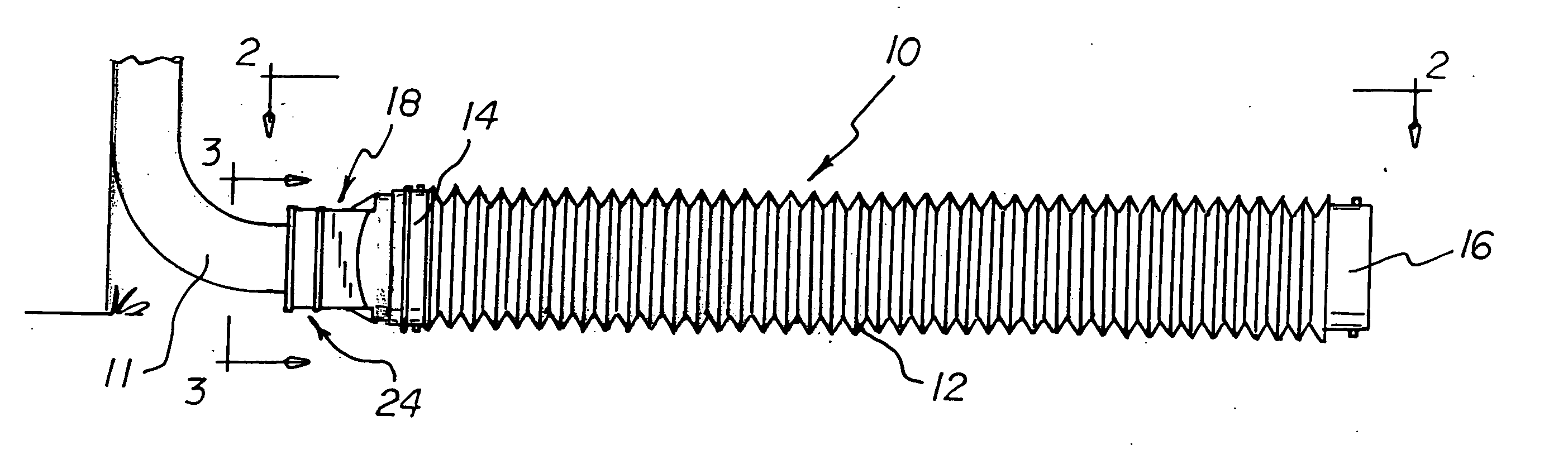
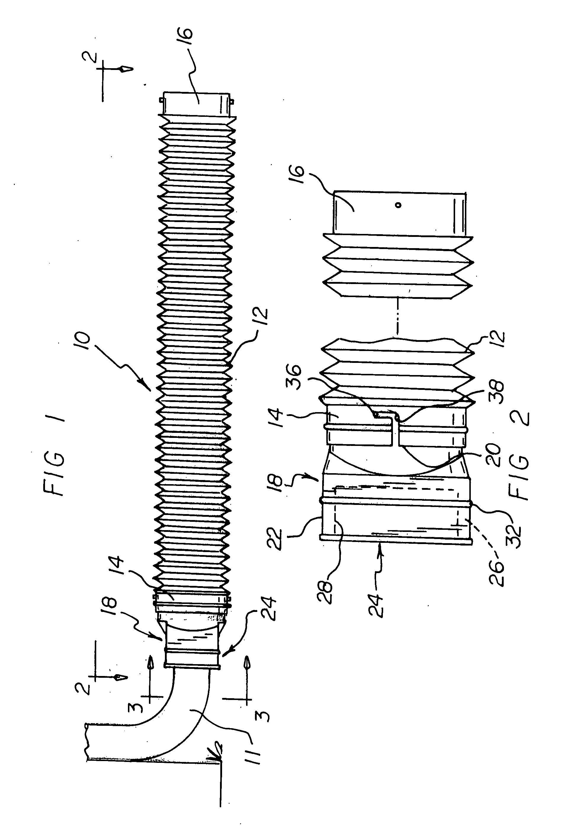
[0054] With reference to the drawings, a new and improved flexible downspout connector apparatus embodying the principles and concepts of the present invention will be described.

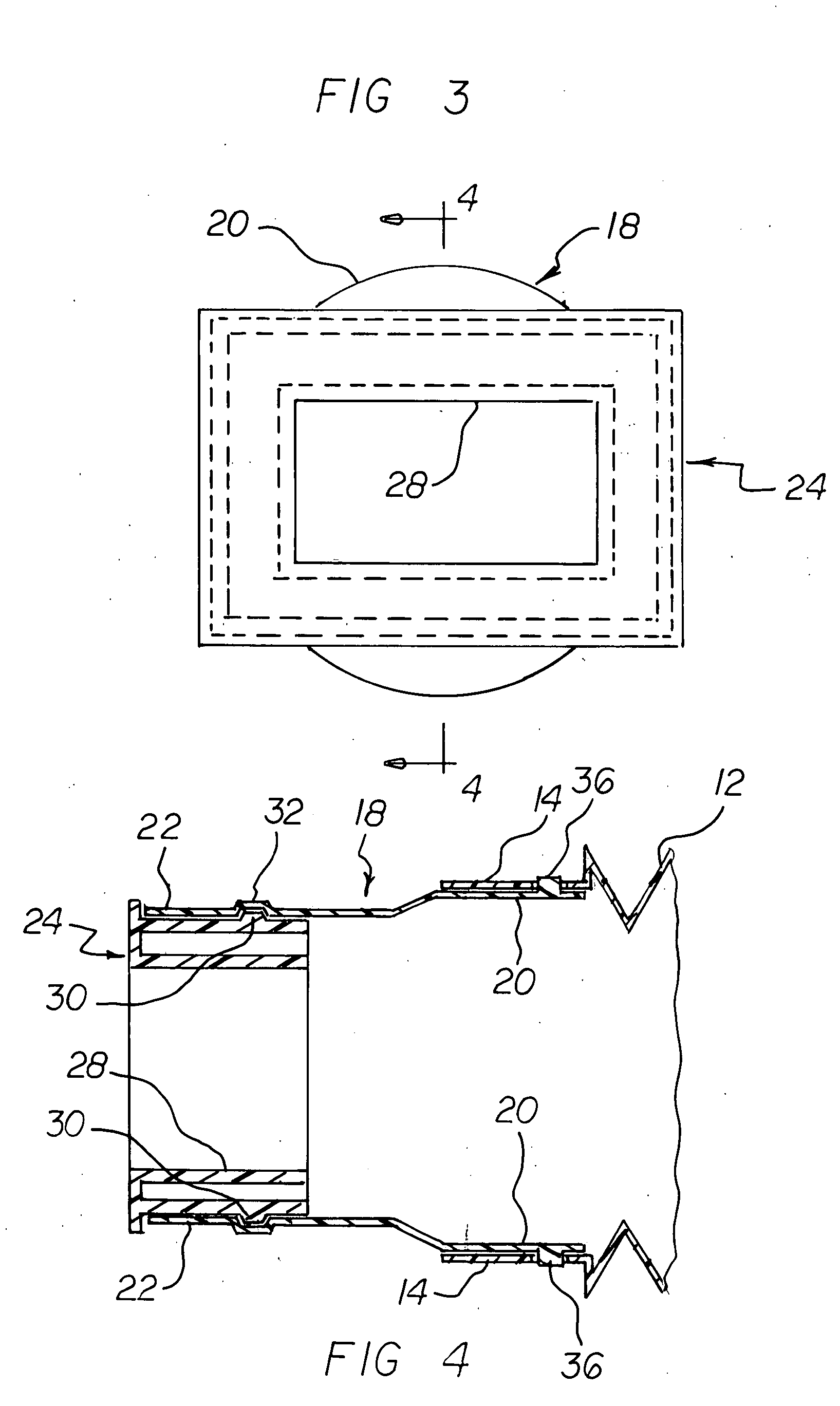
[0055] Turning to FIGS. 1-7, there is shown a first embodiment of the flexible downspout connector apparatus of the invention generally designated by reference numeral 10. In the first embodiment, flexible downspout connector apparatus 10 includes a flexible extension pipe 12 which includes a first pipe connector 14 located at a first end of the flexible extension pipe 12 and which includes a second pipe connector 16 located at a second end of the flexible extension pipe 12. A central portion of pipe 12 includes the usual conventional corrugations that enable the pipe to be flexible and to assume a wide variety of bent shapes. A first adapter member 18 includes an adapter-to-pipe connector portion 20 at one end of the first adapter member 18 and includes a first-size adapter connector portion 22 located at ...


PUM


Abstract

A flexible downspout connector apparatus includes a flexible extension pipe, and a first adapter member and a second adapter member, both nested together at one end of the pipe. The first adapter member includes a connection portion for connecting to a downspout outlet end of a first size, and the second adapter member includes a connection portion for connecting to a downspout outlet of a second size. The second adapter member is releasably telescoped with respect to the first adapter member and may be left in place or easily removed at the option of the user to accommodate for different downspout outlet end sizes.

Description

RELATED APPLICATION [0001] The present application is a continuation-in-part (CIP) of my prior pending U.S. patent application Ser. No. 11 / 211,121, filed Aug. 24, 2005.BACKGROUND OF THE INVENTION [0002] 1. Field of the Invention [0003] The present invention relates generally to flexible extensions for downspouts and, more particularly, to flexible downspout extensions that are especially adapted for connection to different downspouts having different sizes. [0004] 2. Description of the Prior Art [0005] It is well known in the art to connect a flexible extension to a downspout in order to carry drainage water from a gutter and downspout to a location away from a building. In this respect, throughout the years, a number of innovations have been developed relating to flexible extensions connected to downspouts, and the following U.S. and foreign patents are representative of some of those innovations: U.S. Pat. Nos. 2,814,529, 3,076,669, 3,623,500, 3,929,165, 3,966,121, 5,358,006, 5,37...

Claims


Application Information

Patent Timeline
Patent Type & Authority Applications(United States)
IPC IPC(8): F16L51/02
CPCE04D2013/0806E04D13/08F16L25/0009F16L37/248F16L51/025F16L25/14
Inventor CRAWFORD, CAROLE
Owner TAT ONE SOURCE LLC
Why Eureka
Try Eureka