Methods for driving electro-optic displays

a technology of electro-optic displays and drives, applied in the direction of instruments, computing, electric digital data processing, etc., can solve the problem that the waveforms used to drive pixels of electro-optic displays from one optical state to another may be quite complex

Inactive Publication Date: 2008-01-31
E INK CORPORATION
View PDF99 Cites 399 Cited by
  • Summary
  • Abstract
  • Description
  • Claims
  • Application Information

AI Technical Summary

Benefits of technology

[0046] Variant (c) may require further explanation. Consider the not-uncommon situation of a series of images in which a single object, or small number of objects, are moving against an essentially static background; more specifically, consider a series of monochrome images in which a black plane is moving against a white sky. To effect a transition between successive images, certain pixels around the periphery of the plane must be rewritten. To avoid visually-distracting effects, it may be desirable to apply the reinforcing pulses to black pixels representing the plane, but not to black pixels representing the ground beneath. Similarly, if a display is configured as a series of essentially independent windows, it may be desirable to use a drive scheme in which a “global” updating method is applied to each window independently.
[0047] As a

Problems solved by technology

As discussed in the various applications and patents mentioned in the “Reference to Related Applications” section above, waveforms used to d

Method used


Image

  • Methods for driving electro-optic displays
  • Methods for driving electro-optic displays
  • Methods for driving electro-optic displays

Examples


Embodiment Construction

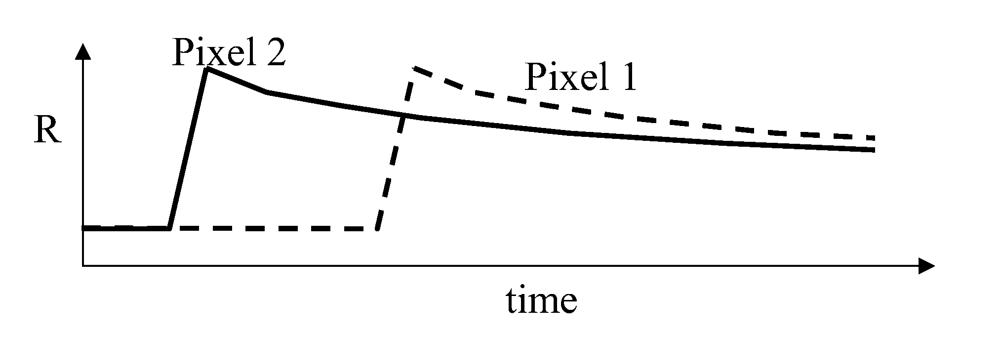
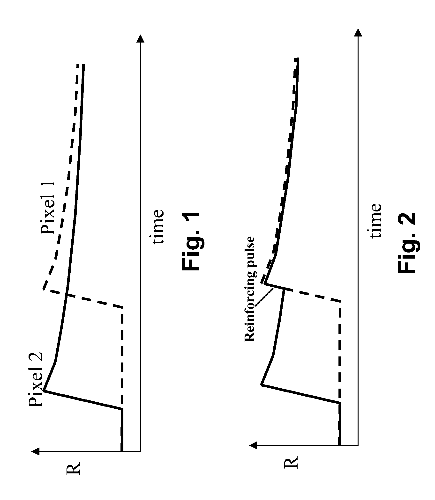
[0067] As already indicated, a first aspect of this invention relates to a method of driving a bistable electro-optic display in which a reinforcing pulse, which does not effect a gross change in the optical state of a pixel, is applied to one or more pixels during or shortly after the application to another pixel of a drive pulse which does change the optical state of that pixel. The reinforcing pulse serves to match the color of the pixel receiving the reinforcing pulse to that of the pixel receiving the drive pulse and, if the two pixels are edge-adjacent, reduces edge ghosting between the two pixels.

[0068] As compared with the refresh pulse driving method of the aforementioned 2005 / 0270261, the present method may reduce the number of reinforcing pulses needed, since if the display is not updated for a long period, no reinforcing pulses will be applied. (It is of course possible to combine the present methods with the refresh pulse method by ensuring that, if any pixel does not ...


PUM


Abstract

Methods are provided for of driving a bistable electro-optic display having at least first and second pixels separated by an inter-pixel gap. In one method, there is applied to the first pixel a drive pulse which drives the pixel to one extreme optical state, and there is applied to the second pixel, which is in this extreme optical state, a reinforcing pulse of the same polarity as the drive pulse. In a second method, a drive pulse applied to the first pixel drives that pixel away from one extreme optical state, and an inverse reinforcing pulse applied to the second pixel is of opposite polarity to the drive pulse. The drive methods reduce edge ghosting or blooming.

Description

REFERENCE TO RELATED APPLICATIONS [0001] This application claims benefit of copending Application Ser. No. 60 / 803,305, filed May 26, 2006, and of copending Application Ser. No. 60 / 804,491, filed Jun. 12, 2006. [0002] This application is a continuation-in-part of copending application Ser. No. 11 / 611,324, filed Dec. 15, 2006 (Publication No. 2007 / 0091418), which is itself a divisional of application Ser. No. 10 / 249,973, filed May 23, 2003 (now U.S. Pat. No. 7,193,625, issued Mar. 20, 2007), which claims benefit of Application Ser. No. 60 / 319,315, filed Jun. 13, 2002 and copending Application Ser. No. 60 / 319,321, filed Jun. 18, 2002. [0003] This application is also related to application Ser. No. 10 / 065,795, filed Nov. 20, 2002 (now U.S. Pat. No. 7,012,600, issued Mar. 14, 2006), which is itself is a continuation-in-part of application Ser. No. 09 / 561,424, filed Apr. 28, 2000 (now U.S. Pat. No. 6,531,997, issued Mar. 11, 2003), which is itself a continuation-in-part of copending appli...

Claims


Application Information

Patent Timeline
IPC IPC(8): H04N1/46
CPCH04N1/46G09G3/344G09G2310/061G09G2320/02G09G2330/022
Inventor GATES, ELIZABETH M.AMUNDSON, KARL R.
Owner E INK CORPORATION
Why Eureka
Try Eureka