
Printer

a printing machine and printing plate technology, applied in the field of printing machines, can solve the problems of increasing the time required for printing each printing sheet and the extremely low printing speed, and achieve the effect of preventing the disorder of printed images

Inactive Publication Date: 2008-01-31
SEIKO EPSON CORP
View PDF7 Cites 3 Cited by
  • Summary
  • Abstract
  • Description
  • Claims
  • Application Information

AI Technical Summary

Benefits of technology

The invention is a printer that uses a belt and multiple printer heads to print on a printing medium. It includes a detection system that detects the meandering (mechanical movement) of the printing medium and generates correction data to prevent disorder of the printed image due to the meandering. The correction data is generated based on the detected meandering and the difference between the detected meandering and a predetermined reference time-series data. The printer also includes a detection section that detects the time-series data for the meandering value of the printing medium and a position detection section that detects the position of the width-directional end of the endless belt. The invention improves printing speed and prevents disorder of the printed image due to meandering of the printing medium.

Problems solved by technology

Therefore, the time required for printing of each printing sheet increases.
When the number of sheets to be printed is large, there is a problem that the printing speed is extremely decreased.

Method used


Image

  • Printer
  • Printer
  • Printer

Examples


first embodiment

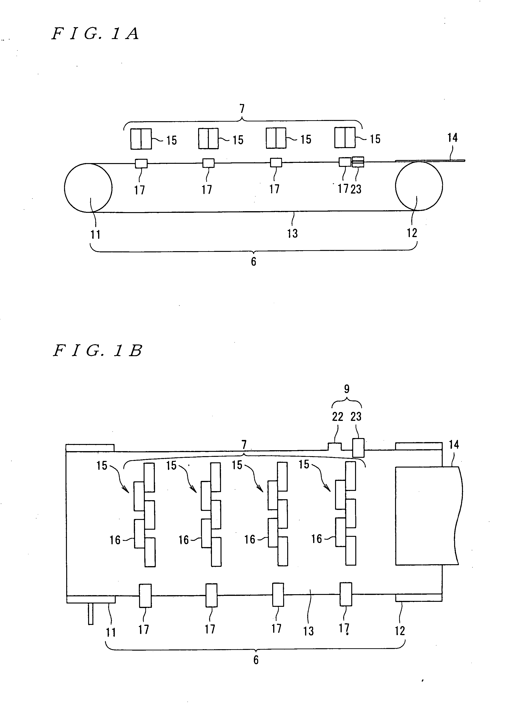
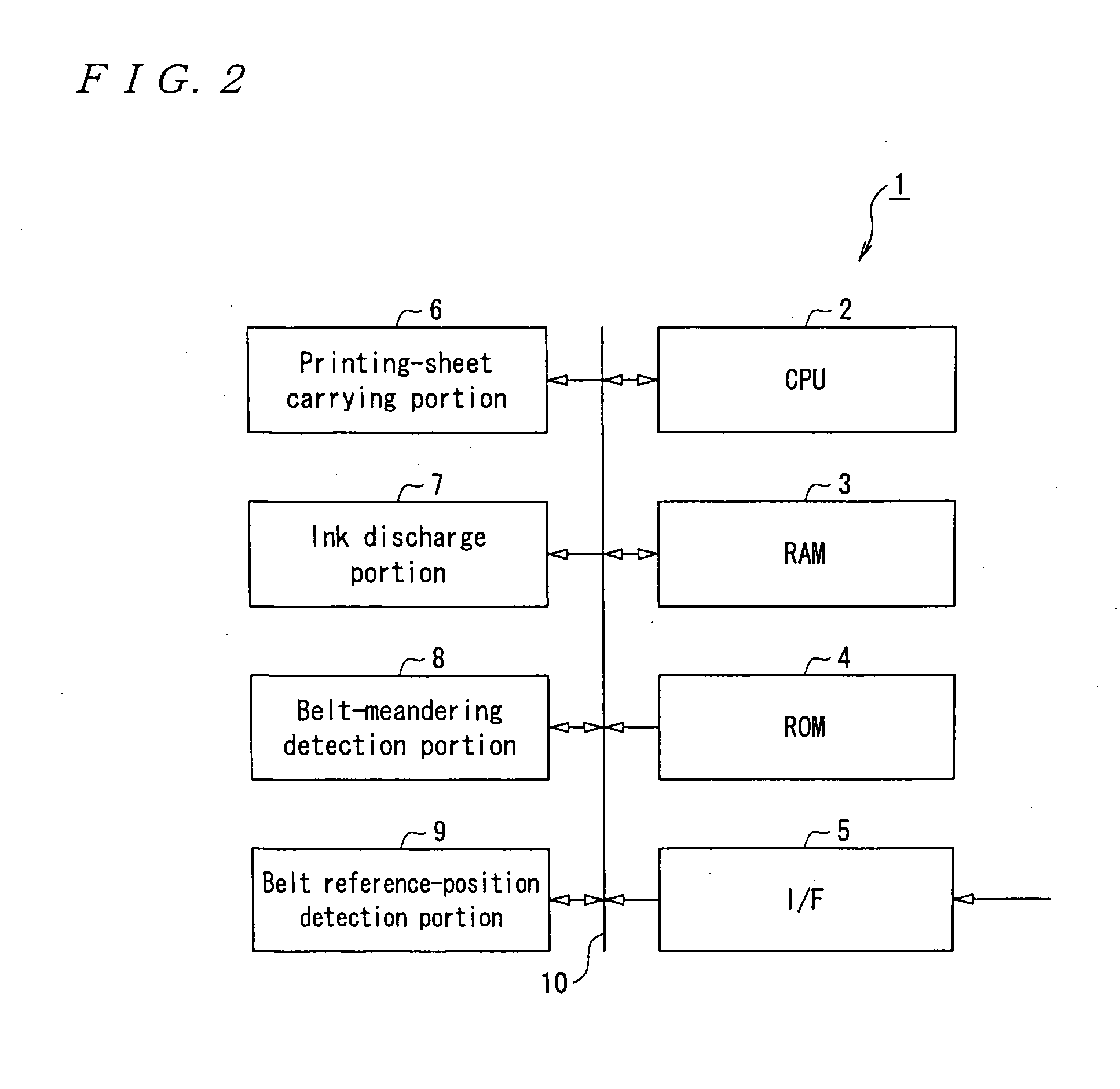
[0034]FIGS. 1A and 1B are a side view and a top view showing the appearance of a line printer of first embodiment and FIG. 2 is a block diagram showing an internal configuration of the line printer of the first embodiment. As shown in FIG. 2, the line printer 1 is constituted by including a CPU (Central Processing Unit) 2, RAM (Random Access Memory) 3, ROM (Read Only Memory) 4, I / F (InterFace) 5, printing-sheet carrying portion 6, ink discharge portion 7, belt meandering detection portion 8, and belt reference-position detection portion 9 and the portions are mutually connected by a bus 10 so that data can be supplied and received.

[0035] Among these portions, the CPU 2 reads various programs and data from the ROM 4 when a printing execution instruction (to be described later) from the I / F 5, develops the programs in a work area formed in the RAM 3, and executes the printing execution processing for controlling the portions so that the information on an image or a character correspo...

second embodiment

[0061] Then, a line printer 1 of second embodiment is described below.

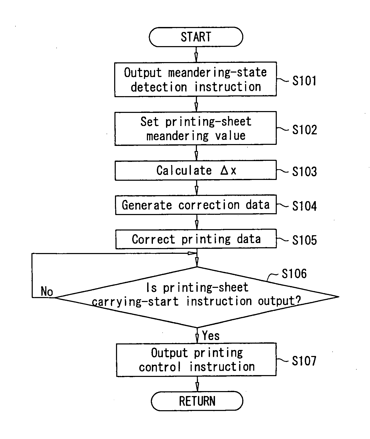
[0062] This embodiment is different from the first embodiment in that the time-series data for the meandering value of the printing sheet 14 is detected when power is supplied to the printer. Specifically, when power is supplied to the printer, the CPU 2 is made to execute printing execution processing, steps S401 to S405 are added before step S101 for printing execution processing, and step 406 is added after step S107.

[0063] The second embodiment includes many configurations same as those of the first embodiment. The same configuration is provided with the same symbol and its detailed description is omitted.

[0064] First, in step S401, a meandering-state detection instruction is output to the belt meandering detection portion 8. When this arithmetic processing is first executed, printing data including the timing, frequency, and dot size for discharging ink drips for each nozzle is generated and the generated ...


PUM


Abstract

A printer for printing on a medium on an endless belt by printer heads includes: a generator generating printing data for each printer head; a detector detecting time-series data for the meandering of the medium; a generator generating correction data preventing disorder of a printed image due to the meandering; and a controller operating each printer head according to the correction and printing data, wherein the correction-data generator selects a specific difference between factors in the time when the time-series and predetermined time-series data are related and newly generates correction data corresponding to the selected factor, wherein a replacement section replaces a factor in the time corresponding to the specific factor of the reference time-series data with the specific factor, and the time-series-data detection section detects the time-series data when power is supplied to the printer.

Description

CROSS-REFERENCE TO RELATED APPLICATIONS [0001] This application is a divisional of U.S. patent application Ser. No. 11 / 088,040 filed on Mar. 23, 2005, which claims the benefit of Japanese Patent Application No. 2004-099577 filed Mar. 30, 2004. The disclosures of the above applications are incorporated herein by reference.BACKGROUND OF THE INVENTION [0002] 1. Field of the Invention [0003] The present invention relates to a printer for sequentially performing printing on a printing medium by a plurality of printer heads. [0004] 2. Description of Related Art [0005] A printer is conventionally known which has a plurality of printer heads capable of printing different colors and sequentially prints a printing sheet by the printer heads. [0006] Moreover, some of the above printers are respectively constituted so that disorder of a printed image due to meandering of a printing sheet is prevented. For example, JP10-35021A discloses that a resist mark is printed on the both margins of a prin...

Claims


Application Information

Patent Timeline
Patent Type & Authority Applications(United States)
IPC IPC(8): B41J29/38B41J3/28B41J11/00H04N1/047H04N1/12H04N1/193
CPCB41J3/28B41J3/543B41J11/007B41J11/008B41J29/38H04N2201/04789H04N1/12H04N1/193H04N1/506H04N2201/04729H04N2201/04731H04N1/047H04N2201/0471H04N2201/04734H04N2201/04741H04N2201/0472H04N2201/04732H04N2201/0315H04N2201/04758H04N2201/02439H04N2201/04794
Inventor KOIKE, YOSHIKAZU
Owner SEIKO EPSON CORP
Learn More