Method and apparatus for conducting Raman spectroscopy

a raman spectroscopy and raman spectroscopy technology, applied in the direction of spectrometry/spectrophotometry/monochromators, optical radiation measurement, instruments, etc., can solve the problems of raman spectroscopy systems, laser light delivery to specimens, and collection of raman signatures

Active Publication Date: 2008-01-31
AHURA CORP
View PDF44 Cites 13 Cited by
  • Summary
  • Abstract
  • Description
  • Claims
  • Application Information

AI Technical Summary

Benefits of technology

[0018] And in one preferred embodiment of the invention, a novel optical probe delivery system is provided which offers three unique modes of use for exciting and collecting light from the specimen under test, all encompassed with one optical probe design. In a first mode of use, the Raman probe allows the user to maintain distance from the specimen by using a conical standoff, which provides both distance control and laser safety by limiting the exposed beams. The second mode of use allows the user to remove the conical standoff so as to maintain distance control by hand or other means. The third mode of use allows a specimen vial to be inserted directly within the probe optics assembly.

Problems solved by technology

Unfortunately, a number of problems exist with respect to current Raman spectroscopy systems.
For example, a persistent problem in existing Raman spectroscopy systems is the delivery of laser light to the specimen and the collection of the Raman signature from the specimen.
Among other things, these problems include space limitations in portable Raman systems, signal distortions introduced into the system due to Amplified Spontaneous Emission (ASE) from the laser sources, etc.
However, the use of these optical fibers can introduce fluorescence and Raleigh and Raman scatterings generated through interactions in the optical fibers.

Method used


Image

  • Method and apparatus for conducting Raman spectroscopy
  • Method and apparatus for conducting Raman spectroscopy
  • Method and apparatus for conducting Raman spectroscopy

Examples


Embodiment Construction

Novel Raman Spectroscope

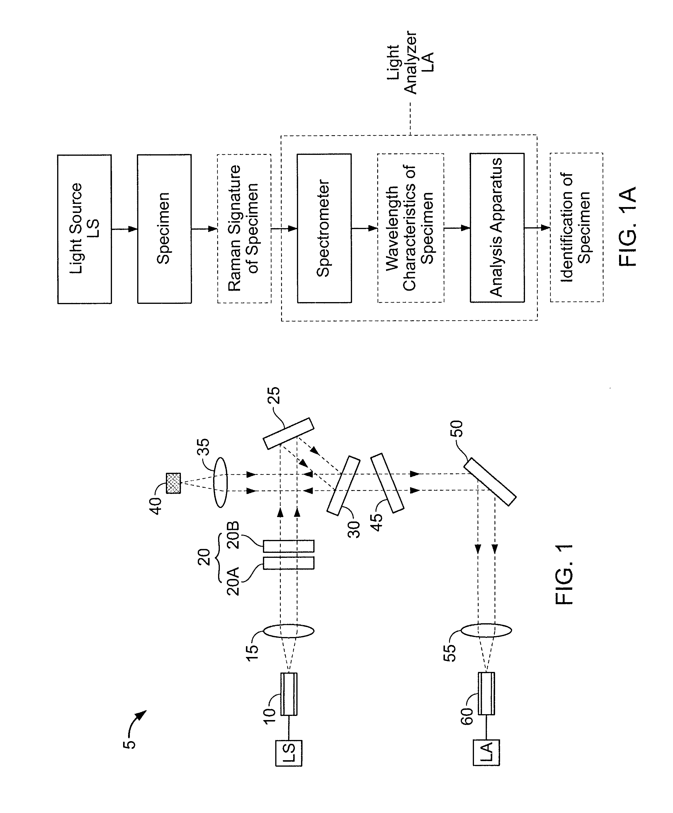
[0065] Looking first at FIG. 1, there is shown a novel Raman probe 5. The excitation light source LS in this arrangement may be, for example, one or more 785 nm semiconductor lasers with limited linewidths. However, the Raman probe 5 may also use any other laser source as the excitation light source LS as long as the laser source is compatible with Raman spectroscopy detection techniques. The output of excitation light source LS is delivered through optical fiber 10 and collimated through lens 15. A bandpass filter 20 (or multiple combination of bandpass filters 20A, 20B) is used to pass the laser excitation light and to block spurious signals associated with the laser, the fiber, and / or both. The spurious signals associated with the laser generally comprise ASE from the laser, and the spurious signals associated with the fiber generally comprise fluorescence and Raleigh and Raman scatterings generated inside the fiber 10. Preferably bandpass filter 20 is ad...


PUM

PropertyMeasurementUnit
Angle Of Incidenceaaaaaaaaaa
focal lengthaaaaaaaaaa
Ramanaaaaaaaaaa

Abstract

Disclosed herein are Raman probes that include: (a) a first optical fiber for receiving laser excitation light from a light source and transmitting the same; (b) a first filter for receiving light from the first optical fiber and adapted to pass the laser excitation light and to block spurious signals associated with the light; (c) a second filter for receiving light from the first filter and adapted to direct the light toward a specimen; and (d) focusing apparatus for receiving the light from the second filter, focusing the light on the specimen so as to generate the Raman signal, and returning the Raman signal to the second filter. The second filter is further configured so that when the second filter receives the Raman signal from the focusing apparatus, the second filter filters out unwanted laser excitation light before directing the Raman signal to a second optical fiber.

Description

REFERENCE TO PENDING PRIOR PATENT APPLICATIONS [0001] This patent application claims benefit of: [0002] (i) pending prior U.S. Provisional Patent Application Ser. No. 60 / 566,713, filed Apr. 30, 2004 by Peidong Wang et al. for RAMAN SPECTROSCOPY TECHNIQUES OVER OPTICAL FIBERS (Attorney's Docket No. AHURA-22 PROV); and [0003] (ii) pending prior U.S. Provisional Patent Application Ser. No. 60 / 607,735, filed Sep. 7, 2004 by Kevin Knopp et al. for RAMAN PROBE WITH INLINE VIAL CAPABILITY (Attorney's Docket No. AHURA-30 PROV). [0004] The two above-identified patent applications are hereby incorporated herein by reference.FIELD OF THE INVENTION [0005] This invention relates to methods and apparatus for identifying and characterizing substances in general, and more particularly to methods and apparatus for identifying and characterizing substances using Raman spectroscopy. BACKGROUND OF THE INVENTION [0006] Raman spectroscopy is a viable technique for identifying and characterizing a vast ar...

Claims


Application Information

Patent Timeline
Patent Type & Authority Applications(United States)
IPC IPC(8): G01J3/44G01N21/65
CPCG01J3/02G01J3/0218G01J3/0272G01N2021/656G01J3/44G01J2003/1213G01N21/65G01J3/0291
Inventor WANG, PEIDONGVAKHSHOORI, DARYOOSHSHEN, YUKNOPP, KEVIN J.AZIMI, MASUD
Owner AHURA CORP
Why Eureka
Try Eureka