Optical spot geometric parameter determination using calibration targets

a technology of geometric parameter and optical spot, applied in the field of processing system, can solve the problems of affecting the matching performance of optical metrology tools, and conventional approaches to optical metrology do not have a satisfactory solution

Inactive Publication Date: 2008-01-31
GLOBALFOUNDRIES INC
View PDF6 Cites 6 Cited by
  • Summary
  • Abstract
  • Description
  • Claims
  • Application Information

AI Technical Summary

Benefits of technology

[0010]A third aspect of the disclosure is directed to a calibration target for measuring a size of an optical spot of a light beam, the calibration target comprising: a first portion, a dimension of which in a first axis systematically decreases along a second axis; a second portion; and a third portion; wherein the second portion and the third portion extend along opposite sides of the first portion and are separated by the first portion in the first axis, and include a material of different optical response than that of the first portion.

Problems solved by technology

As a consequence, for example, the sizes of the optical spots of optical metrology tools affects the matching performance of the optical metrology tools.
Conventional approaches to optical metrology do not have a satisfactory solution to characterize a geometric parameter of an optical spot and or or a level of symmetry of the optical spot.

Method used


Image

  • Optical spot geometric parameter determination using calibration targets
  • Optical spot geometric parameter determination using calibration targets
  • Optical spot geometric parameter determination using calibration targets

Examples


Embodiment Construction

[0020]The following detailed description of embodiments refers to the accompanying drawings, which illustrate specific embodiments of the disclosure. Other embodiments having different structures and operations do not depart from the scope of the present disclosure.

1. SYSTEM OVERVIEW

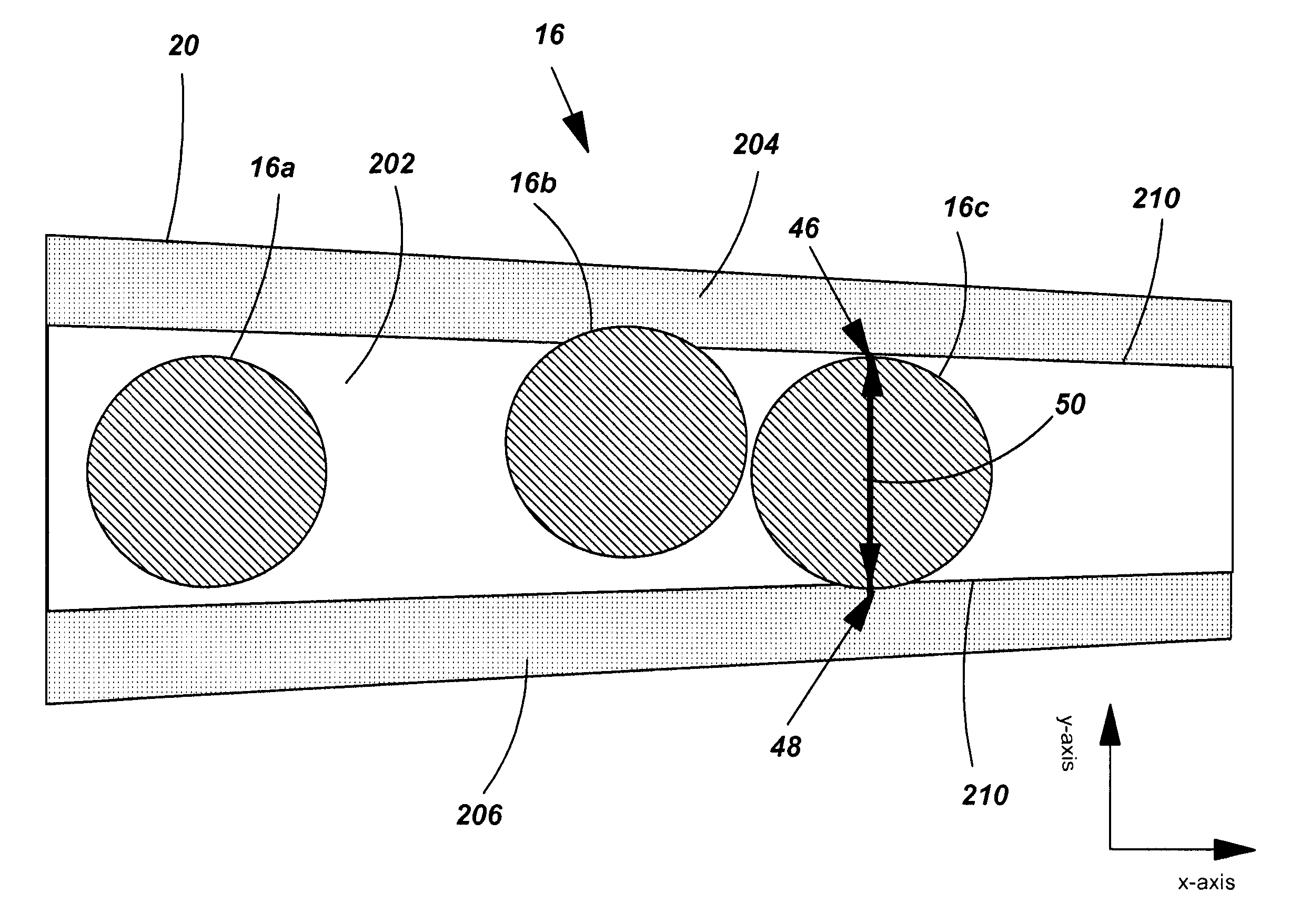
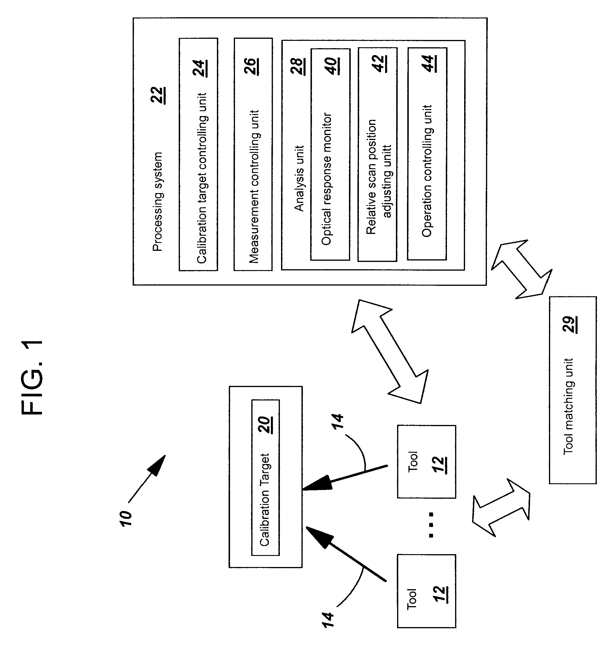
[0021]FIG. 1 shows a block diagram of a system 10 according to an embodiment of the invention. System 10 includes multiple optical metrology tools (tool) 12. Each tool 12 can produce a light beam 14 having an optical spot 16 (shown in FIG. 2) on a calibration target 20. System 10 includes a processing system 22 including a calibration target controlling unit 24, a measurement controlling unit 26, an analysis unit 28 including an optical response monitor 40, a relative scan position adjusting unit 42 and an operation controlling unit 44. System 10 also includes a tool matching unit 29.

2. MEASURING OPTICAL SPOT SIZE

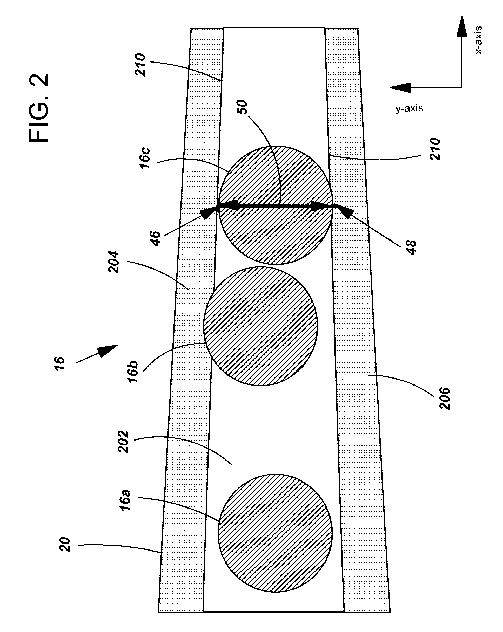
[0022]FIG. 2 shows a calibration target 20 with multiple optical spots 16 thereon. Calibrati...


PUM


Abstract

A method, system and computer program product for determining a geometric parameter of an optical spot of a light beam are disclosed. A method comprises: providing a calibration target, the calibration target including a systematic variation in a parameter; measuring the calibration target with respect to the systematic variation using the light beam to obtain a plurality of measurements; and analyzing the measurements and the systematic variation to determine the geometric parameter of the optical spot.

Description

BACKGROUND OF THE DISCLOSURE[0001]1. Technical Field[0002]The present disclosure relates in general to a processing system, and more particularly to determining a geometric parameter of an optical spot of a light beam of an optical metrology tool used in the processing system.[0003]2. Background Art[0004]Utilization of optical metrology in semiconductor manufacturing has grown significantly over the past several years. The technology provides capabilities to conduct measurements of a wide variety of critical device parameters, including, e.g., critical dimensions, depths and sidewall angles. Benefits of optical metrology include non-contact measurement capability that can be performed very quickly.[0005]For optical metrology tools to yield reliable measurements, it is necessary that the tools produce well defined light beams, and collect the optical response for analysis, as designed. The size of the optical spot of the produced light beam, which is defined as the area illuminated b...

Claims


Application Information

Patent Timeline
Patent Type & Authority Applications(United States)
IPC IPC(8): G01B9/08
CPCG03F7/70516
Inventor ZANGOOIE, SHAHINYOUNG, ROGER M.ZHOU, LINBOTTINI, CLEMENTEFIEGE, RONALD D.
Owner GLOBALFOUNDRIES INC
Why Eureka
Try Eureka