Security barrier

Inactive Publication Date: 2008-01-31
JESSOP MERL K
View PDF13 Cites 4 Cited by
  • Summary
  • Abstract
  • Description
  • Claims
  • Application Information

AI Technical Summary

Benefits of technology

[0009]In one form of the invention, a draw bolt extends through the cover of the ground sleeve and is adapted to threadably engage the upper threaded portion of the tension bar. With this construction, with the jam member positioned within the ground sleeve, rotation of the draw bolt will cause the jam member to move upwardly within the ground sleeve in a manner to cause the tapered surface of the jam member to move into engagement with the tapered surface of the ground sleeve. Continued upward movement of the jam member through continued rotation of the draw bolt will cause the jam member to move into jamming engagement with the inner wall of the ground sleeve thereby securely locking the bollar

Problems solved by technology

Removal of this type of bollard is only achievable with great difficulty and typically such bollards are not removed until the entire unit is replaced.
As a general

Method used


Image

  • Security barrier
  • Security barrier
  • Security barrier

Examples


Example

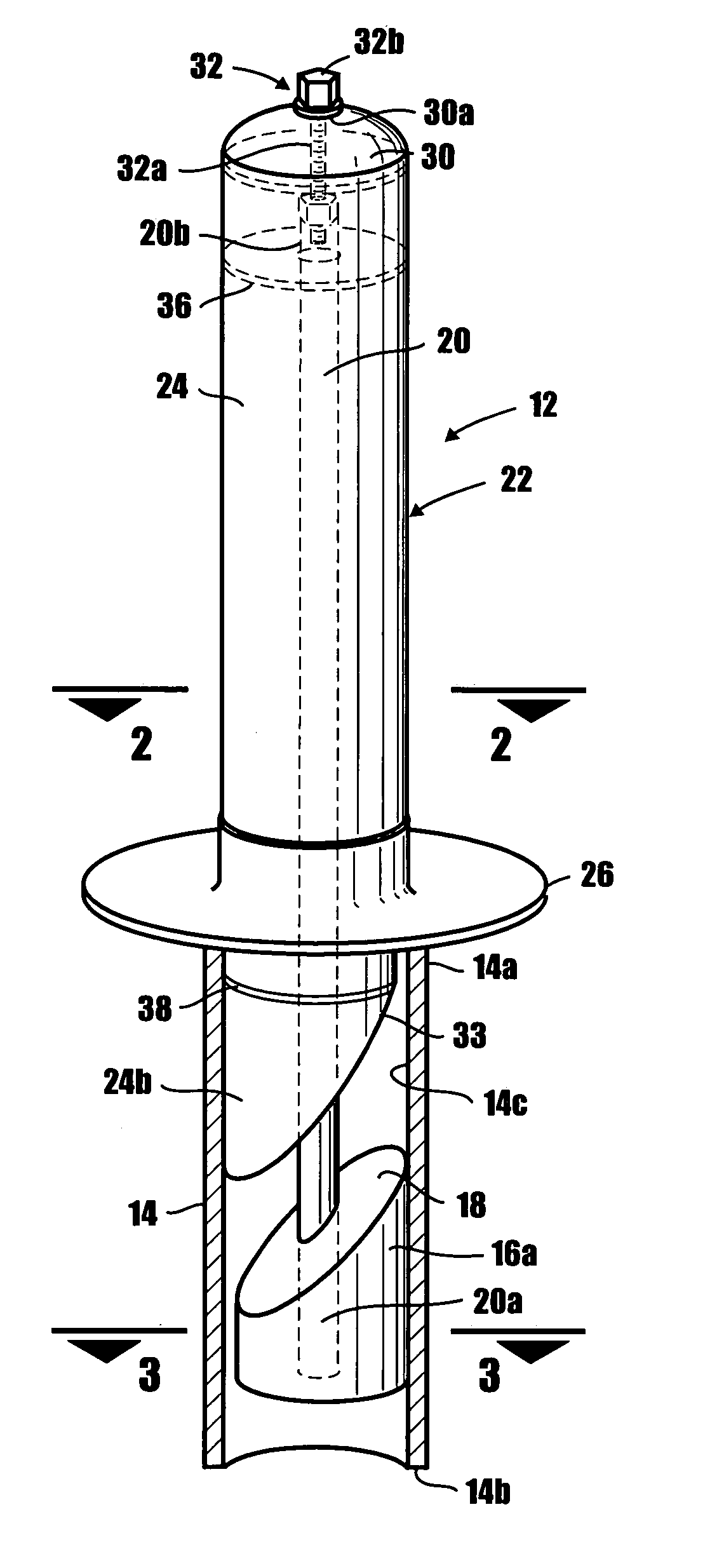
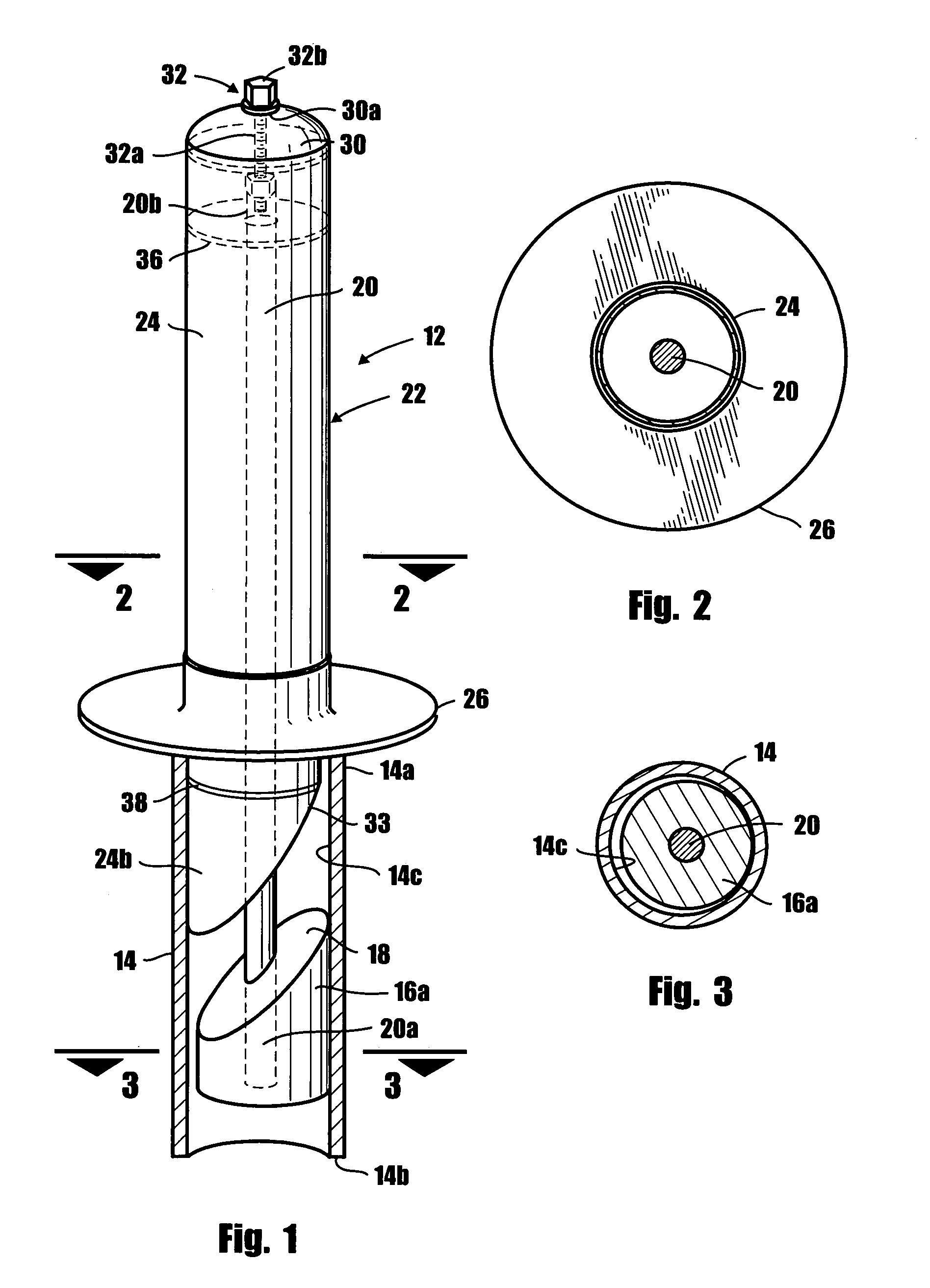
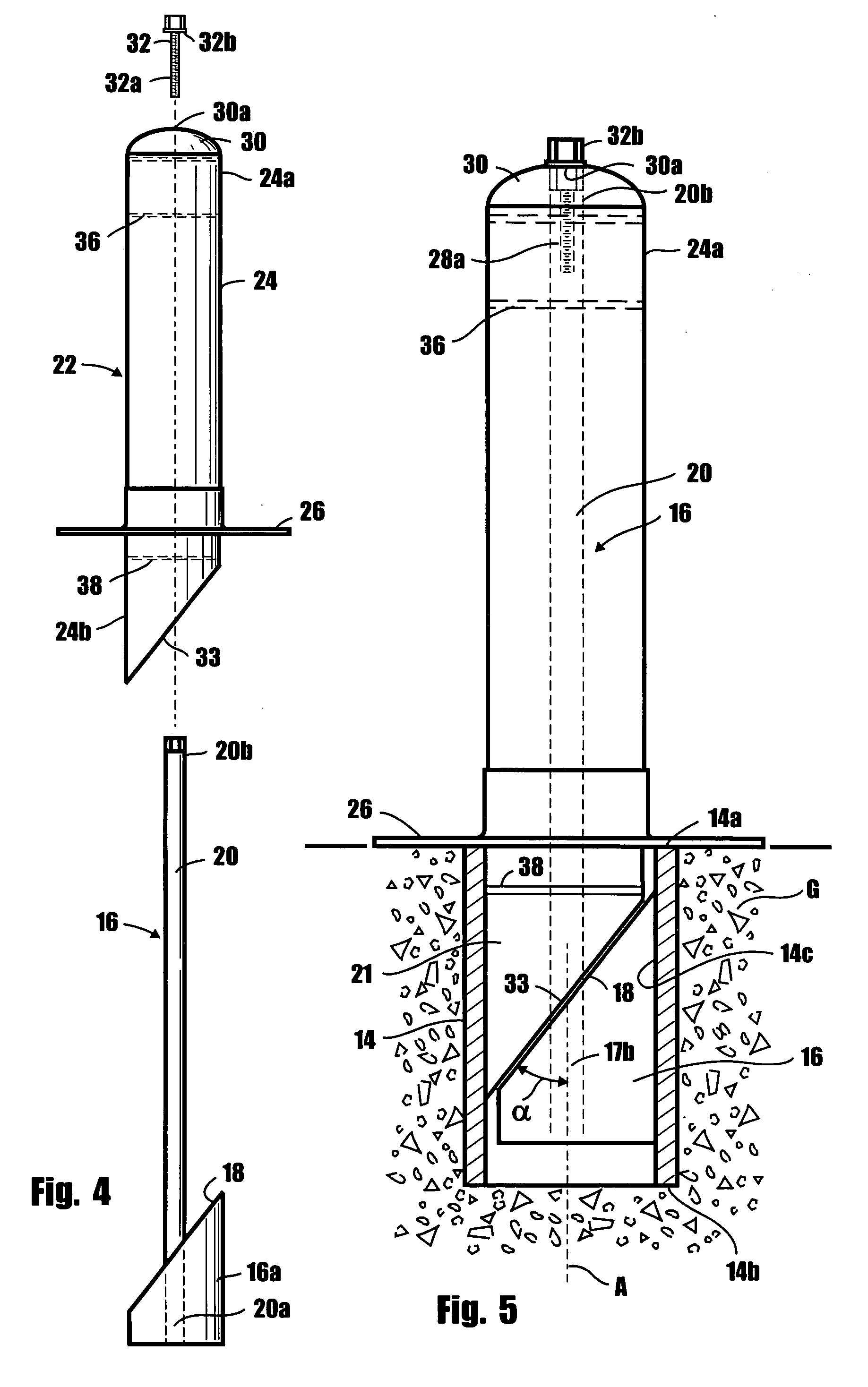
[0022]Referring to the drawings and particularly to FIGS. 1 through 5, one form of the barrier apparatus of the present invention for controlling access to a controlled space is there shown and generally identified by the numeral 12. This form of the apparatus comprises a subterranean tubular sleeve 14 having an upper end 14a and a lower end 14b. As best seen in FIG. 5 of the drawings, sleeve 14 is concreted into the ground “G” in a manner such that upper end 14a is located at finished grade height.

[0023]Receivable within tubular sleeve 14 is a uniquely configured jam assembly 16 (FIG. 4) which is movable within the sleeve from a first, free position shown in FIGS. 1 and 3 to a second jammed position shown in FIG. 5 wherein the generally cylindrically shaped jam member component 16a of the jam assembly 16 is in locked engagement with the inner surface 14c of the tubular sleeve. As illustrated in the drawings, jam member 16a is provided with a tapered, upper surface 18, the purpose o...


PUM


Abstract

A security barrier apparatus that includes a ground sleeve that is concreted into the ground at finish grade height and a uniquely configured jam member that is movable within the ground sleeve from a first free position to a second jammed position in engagement with the inner wall of the tubular sleeve. Connected to the jam member and extending upwardly therefrom is an elongated tension bar having an upper, internally threaded portion that is receivable within the hollow body portion of the apparatus. The jam member includes a tapered wall portion that is mateable with a tapered wall portion provided on the lower portion of the apparatus. A draw bolt extends through the cover of the ground sleeve and is adapted to threadably engage the upper threaded portion of the tension bar. Rotation of the draw bolt will cause the jam member to move upwardly within the ground sleeve in a manner to cause the tapered surface of the jam member to move into jamming engagement with the tapered surface of the ground sleeve securely locking the apparatus in place.

Description

BACKGROUND OF THE INVENTION[0001]1. Field of the Invention[0002]The present invention relates generally to security barriers. More particularly, the invention concerns a barrier having a removable bollard body portion for selectively preventing ingress and egress to a controlled space.[0003]2. Discussion of the Prior Art[0004]A number of different types of devices for controlling parking space access have been suggested in the past. In its simplest form, a cement post is often used as a bollard to protect an exterior wall of a building or some other structure. Removal of this type of bollard is only achievable with great difficulty and typically such bollards are not removed until the entire unit is replaced. However, in many instances it is highly desirable that the bollard be temporarily removed to reconfigure the controlled space or to allow free access to the controlled space for selected periods of time.[0005]Accordingly, various types of removable barrier devices have been des...

Claims


Application Information

Patent Timeline
IPC IPC(8): E01F13/00
CPCE01F13/026
Inventor JESSOP, MERL K.
Owner JESSOP MERL K
Why Eureka
Try Eureka