Multiple-thread screw

a multi-thread screw and thread technology, applied in the direction of screws, threaded fasteners, fastening means, etc., can solve problems such as woodwork piece cracking

Inactive Publication Date: 2008-01-31
JAU YEOU IND
View PDF13 Cites 31 Cited by
  • Summary
  • Abstract
  • Description
  • Claims
  • Application Information

AI Technical Summary

Benefits of technology

[0005]Therefore, the object of the present invention is to provide a multiple-thread screw that can overcome the aforesaid drawback of the prior art.

Problems solved by technology

The conventional screw 2 is disadvantageous in that the shavings resulting from penetration of the screw 2 into the wooden workpiece 20 cannot be efficiently expelled out of the clearance between the screw 2 and the wooden workpiece 20, thereby resulting in cracking of the wooden workpiece 20.

Method used


Image

  • Multiple-thread screw
  • Multiple-thread screw
  • Multiple-thread screw

Examples


Embodiment Construction

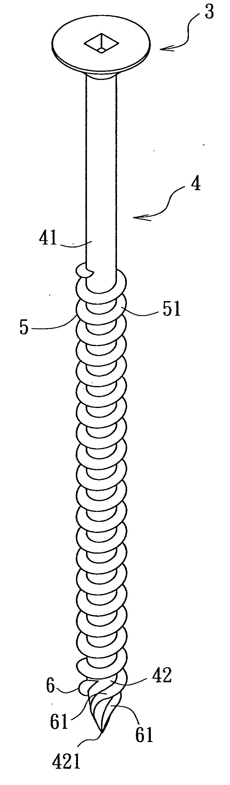
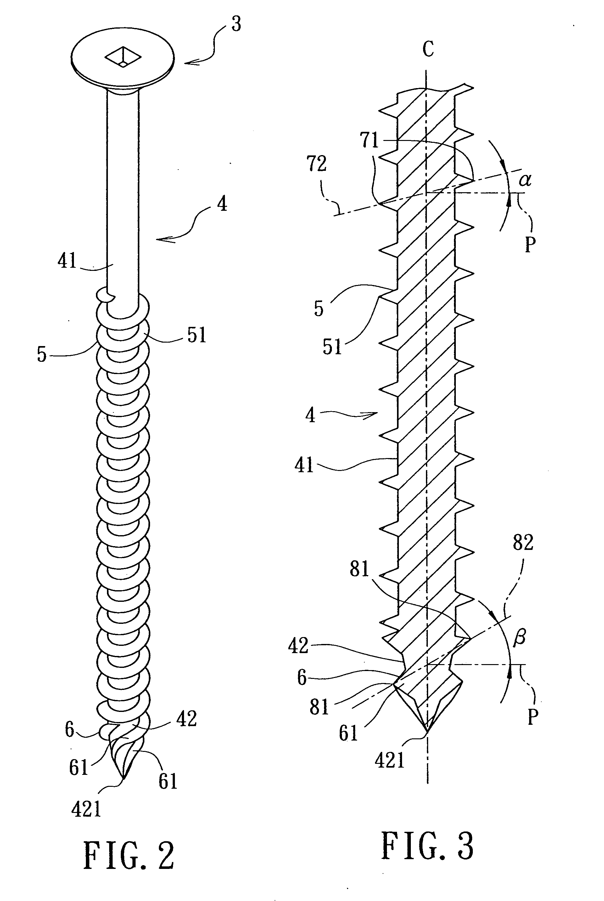
[0015]FIGS. 2 to 4 illustrate the first preferred embodiment of a wooden multiple-thread screw according to this invention. The multiple-thread screw includes: a head 3; a shank 4 extending from the head 3 and having a tapered end portion 42 and a non-tapered portion 41 extending from the tapered end portion 42, the shank 4 defining an axis (C) and a radial plane (P) radiating from the axis (C); a first thread unit 5 including at least one first spiral thread 51 formed on the non-tapered portion 41 of the shank 4 and having thread turns, each of which has two diametrically disposed points 71 that cooperatively define a diametrical line 72 inclined at a first thread angle a with respect to the radial plane (P); and a second thread unit 6 having a double-twist structure that includes two second spiral threads 61 formed on the tapered end portion 42 of the shank 4 and twisted in opposite directions. Each of the second spiral threads 61 has thread turns, each of which has two diametrica...


PUM

PropertyMeasurementUnit
angleaaaaaaaaaa
thread angleaaaaaaaaaa

Abstract

A multiple-thread screw includes: a shank having a tapered end portion and a non-tapered portion, the shank defining an axis and a radial plane radiating from the axis; a first spiral thread formed on the non-tapered portion of the shank and having thread turns, each of which has two diametrically disposed points that cooperatively define a diametrical line inclined at a first thread angle with respect to the radial plane; and two second spiral threads formed on the tapered end portion of the shank and twisted in opposite directions. Each of the second spiral threads has thread turns, each of which has two diametrically disposed points that cooperatively define a diametrical line inclined at a second thread angle with respect to the radial plane. The second thread angle is larger than the first thread angle.

Description

BACKGROUND OF THE INVENTION[0001]1. Field of the Invention[0002]This invention relates to a multiple-thread screw, more particularly to a multiple-thread screw having a first spiral thread defining a first thread angle and a second spiral thread defining a second thread angle larger than the first thread angle.[0003]2. Description of the Related Art[0004]FIG. 1 illustrates a conventional screw 2 for penetrating into a wooden workpiece 20. The screw 2 includes a head 21, a shank 22 extending from the head 21 and having a non-tapered portion 221 and a tapered end portion 222, a spiral thread 23 formed on the non-tapered portion 221 of the shank 22, and a lead blade unit 24 formed on the tapered end portion 222 of the shank 22. The conventional screw 2 is disadvantageous in that the shavings resulting from penetration of the screw 2 into the wooden workpiece 20 cannot be efficiently expelled out of the clearance between the screw 2 and the wooden workpiece 20, thereby resulting in crac...

Claims


Application Information

Patent Timeline
Patent Type & Authority Applications(United States)
IPC IPC(8): F16B25/10
CPCF16B25/0015F16B25/10F16B25/0084F16B25/0047
Inventor CHEN, MING-SHINGLIN, PAU-TEN
Owner JAU YEOU IND
Why Eureka
Try Eureka