Electrically Operated Brake

a technology of brake device and brake plate, which is applied in the direction of braking system, process and machine control, instruments, etc., can solve the problems of reliability problems, insufficient determination of motor torque, and error in positional relationship between contact pin tip and pad surface, so as to reduce the braking force difference, and ensure safe travel of the vehicle

Inactive Publication Date: 2008-02-07
HITACHI LTD
View PDF8 Cites 16 Cited by
  • Summary
  • Abstract
  • Description
  • Claims
  • Application Information

AI Technical Summary

Benefits of technology

[0015] According to the present invention, it is possible to provide a technique for reducing the braking force difference between the right and the left wheel of a vehicle even if the contact position between the a brake pad and a disc rotor is not accurately detected and assure safe travel of the vehicle.
[0016] Moreover, according to the present invention, during the non-brake state, motor currents of a plurality of electrically operated brakes are compared and aligned so as to surely reduce the braking force difference between the electrically operated brakes. Moreover, a motor standard position obtained by the aforementioned operation is stored and the aforementioned operation is repeated a plurality of times so that brakes forces by a plurality of electrically operated brakes are accurately matched.

Problems solved by technology

However, when the motor torque is set to be small, the motor acceleration becomes a small value and the motor acceleration measurement value becomes highly sensitive against the internal fluctuation and the friction state of the power transmission system.
Accordingly, there is a problem that it is difficult to determine the motor torque for sufficiently accurately detecting the pad contact position.
However, when the contact pin and the brake pad are made of different materials, or when the contact pin and the brake pad have different wear speed depending on the contact pin mounting method and the pad wear proceeds, there is a possibility that an error is caused in the positional relationship between the contact pin tip and the pad surface.
Moreover, since a large force is applied to the brake pad, there is a problem of reliability when the contact pin is arranged in the brake pad.
As has been described above, in a vehicle having electrically operated brakes mounted on a plurality of wheels, it is not easy to reduce the braking force difference between the wheels by using the conventional technique.

Method used


Image

  • Electrically Operated Brake
  • Electrically Operated Brake
  • Electrically Operated Brake

Examples


embodiment 1

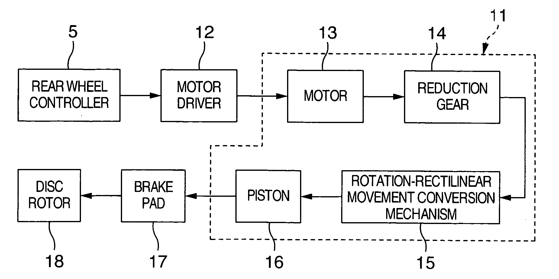
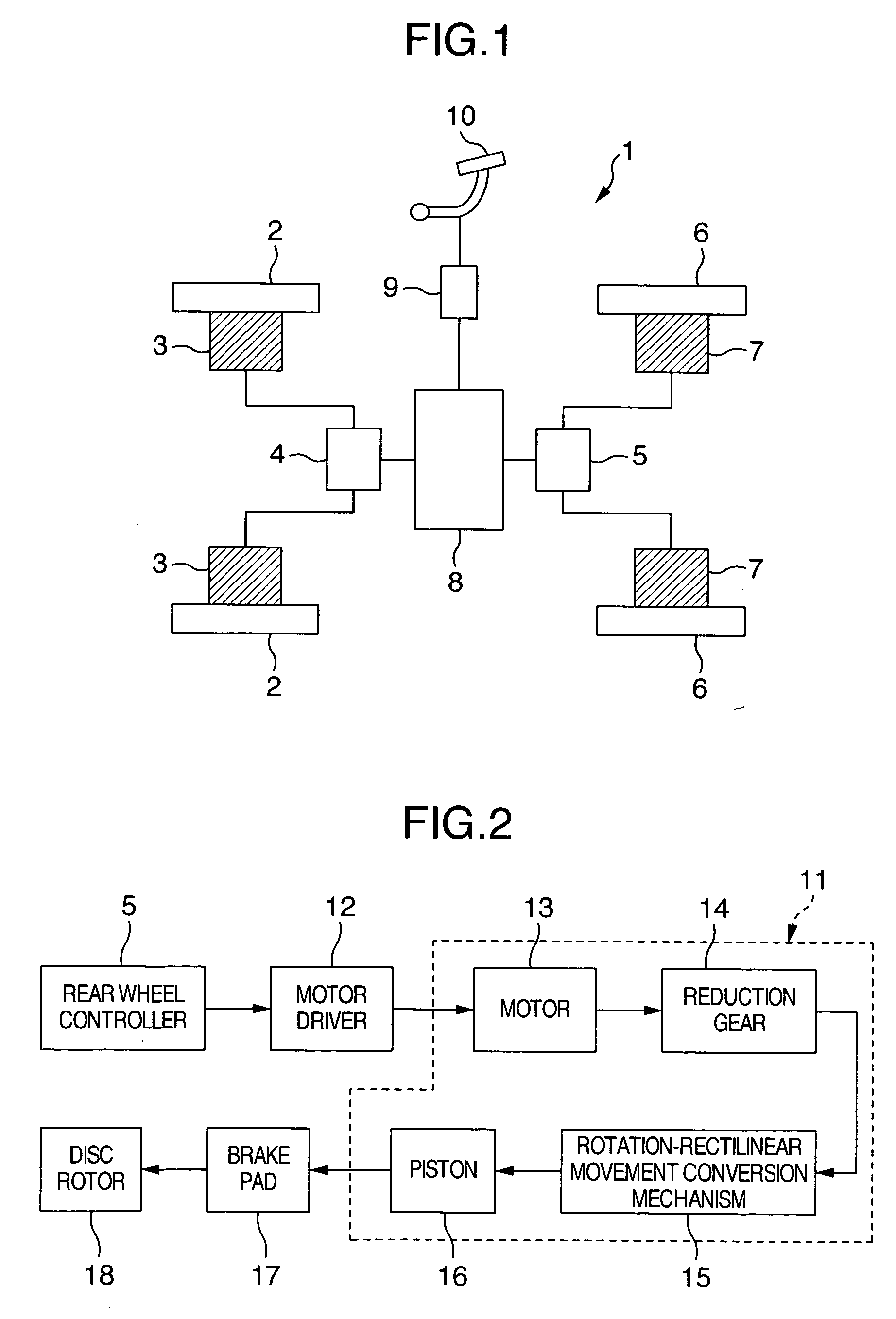
[0027] Description will now be directed to an embodiment of the present invention with reference to FIG. 1 to FIG. 5. FIG. 1 shows a general system configuration of a vehicle in which an electrically operated brake is provided on each of four wheels. In FIG. 1, the electrically operated brake device 1 is formed by front wheel brakes 3 mounted on front wheels 2 of the vehicle, a front wheel controller 4 for controlling the front wheel electrically operated brake 3, rear wheel brakes 7 mounted on rear wheels 6, a rear wheel controller 5 for controlling the electrically operated brakes 7 of the rear wheels, a main controller 8 for controlling the front wheel controller 4 and the rear wheel controller 5, a brake pedal 19 used by a driver to adjust the brake intensity, and a pedal force sensor 9 for measuring the pressing force applied to the brake pedal 10.

[0028] Explanation will be given on operation of each of the components in FIG. 1. In FIG. 1, when the driver presses the brake ped...


PUM


Abstract

An electrically operated brake device in which braking force differences between electrically operated brakes are reduced to prevent unstable vehicle traveling during braking.
Motors 13 of electrically operated brakes are returned to standard positions during the stop of a vehicle and the motor 13 of each of the brakes is driven for a predetermined amount, pressing a brake pad 17 against a disc rotor 18 to produce a braking force.
An electric current value of each motor 13 in the above operation is measured and differences between the values are calculated. Electric current of each motor is increased or decreased so that there is no current difference between the motors 13. Based on a drive amount of each motor in this operation, standard positions of the motors are determined and updated. Repeating the above operations reduces braking force differences between the brakes.

Description

TECHNICAL FIELD [0001] The present invention relates to an electrically operated brake device generating a braking force by operation of an electric motor. BACKGROUND ART [0002] When a brake device for generating a braking force by operation of a motor without using hydraulic means on a plurality of wheels of a vehicle, it is necessary to control the braking force of each wheel separately. Accordingly, if the braking force control is not sufficiently accurate, there is a possibility that a braking force difference may be caused to make the behavior of each wheel unstable. For example, when a braking force difference is caused between the right and the left wheel of a vehicle, a yaw angular velocity is generated upon brake in the vehicle body and a passenger feels unpleasant feeling. Moreover, in the worst case, the vehicle body may spin. [0003] It should be noted that in a case of a train, the right and the left wheel are connected to each other in general, and the braking force dif...

Claims


Application Information

Patent Timeline
Patent Type & Authority Applications(United States)
IPC IPC(8): F16D55/225B60T7/00B60T8/00B60T8/24B60T13/74F16D55/224F16D65/18F16D66/00
CPCB60T8/00B60T13/741B60T8/24
Inventor KAWAHARA, YOSHINARIOHNO, KOUSAKUYOKOYAMA, ATSUSHISASAKI, MITSUHIDE
Owner HITACHI LTD
Why Eureka
Try Eureka