
Adjustable baseboard and molding system

a molding system and adjustable technology, applied in the field of baseboard heaters, can solve the problems of insufficient heat distribution, no suggestion that the baseboard units be used in conjunction with matching, and non-functional molding, and achieve the effect of improving the overall aesthetic appearance or appearance of the system, and enhancing the comfort of the occupants

Inactive Publication Date: 2008-02-07
FRIEDLICH WILLIAM
View PDF61 Cites 15 Cited by
  • Summary
  • Abstract
  • Description
  • Claims
  • Application Information

AI Technical Summary

Benefits of technology

"The present invention provides a baseboard system that includes a baseboard unit and moldings at the ends of the baseboard units. The moldings have a continuous external profile, which enhances the appearance of the installation and makes cleaning easier. The baseboard system can be used in new constructions or retrofits in existing constructions without the need for additional plumbing. It can also be easily installed and removed without damaging the baseboard or the plumbing. The baseboard system provides a continuous heat distribution within the enclosure, improving the comfort level without sacrificing aesthetics. It can be retrofitted in existing constructions without the need for additional plumbing. The baseboard system also allows for the installation of a raceway for low voltage wiring and provides a removable foot for easy sanding or finishing of the floor. The invention provides a baseboard system that is efficient, economical, and easy to install and modify."

Problems solved by technology

However, in both cases, there is no suggestion that baseboard units be used in conjunction with matching, non-functional moldings.
However, shelving is used in conjunction with the ventilating system cabinet so that there is no real symmetry or uniform appearance between the heating cabinet and the adjoining shelving.
However, while the room obtained its required BTUs the heat was not optimally distributed, with the bulk of the heat being provided at the exposed walls.
While this could be achieved with a 10′ baseboard on one exposed wall using the conventional 600 BTU per foot units, there would be an even greater deterioration in the distribution of heat as the heat distribution would be quite uneven in the room making it less comfortable for the occupant(s).
An alternative arrangement of a 4′ baseboard on the 15′ wall and 6′ baseboard on the 20′ wall would be better, but still uneven, and both solutions are less than desirable.

Method used


Image

  • Adjustable baseboard and molding system
  • Adjustable baseboard and molding system
  • Adjustable baseboard and molding system

Examples


Embodiment Construction

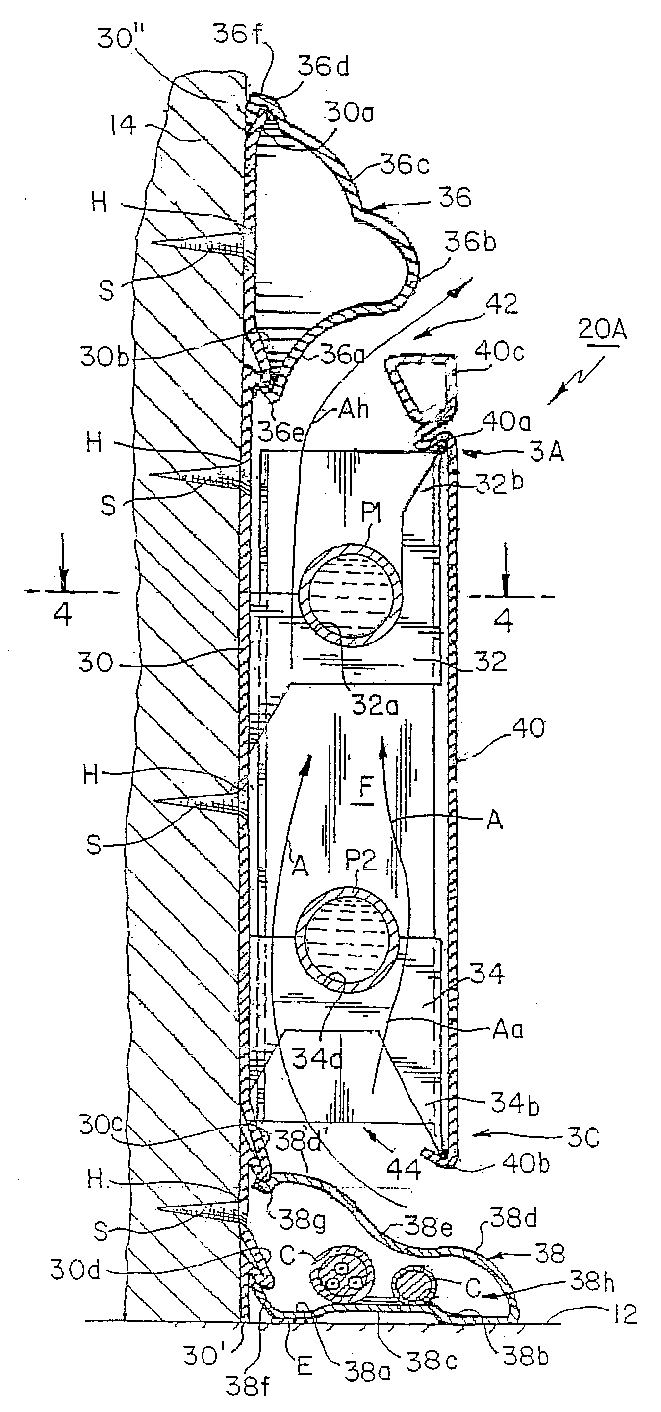
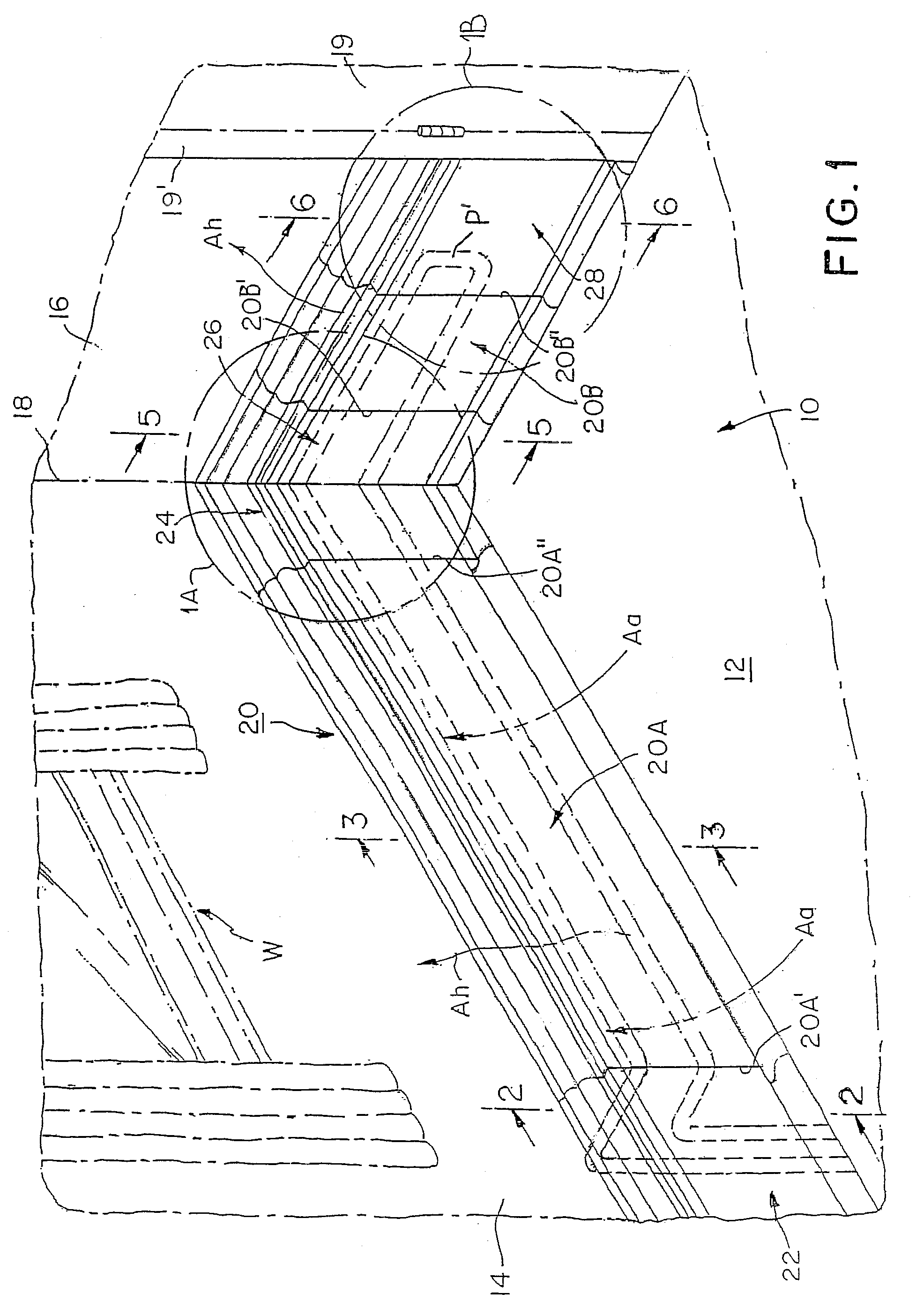
[0051] Referring now more specifically to the drawings, and first referring to FIG. 1, an enclosure or room to be heated is generally designated by the reference numeral 10, a perspective view of only one corner of a typical room being illustrated. It will become evident from the description that follows that the present invention can be used about the entire periphery of a room or only along a portion of a wall of the enclosure.

[0052] The enclosure 10 includes a floor 12 and walls 14 and 16 that meet at a corner 18.

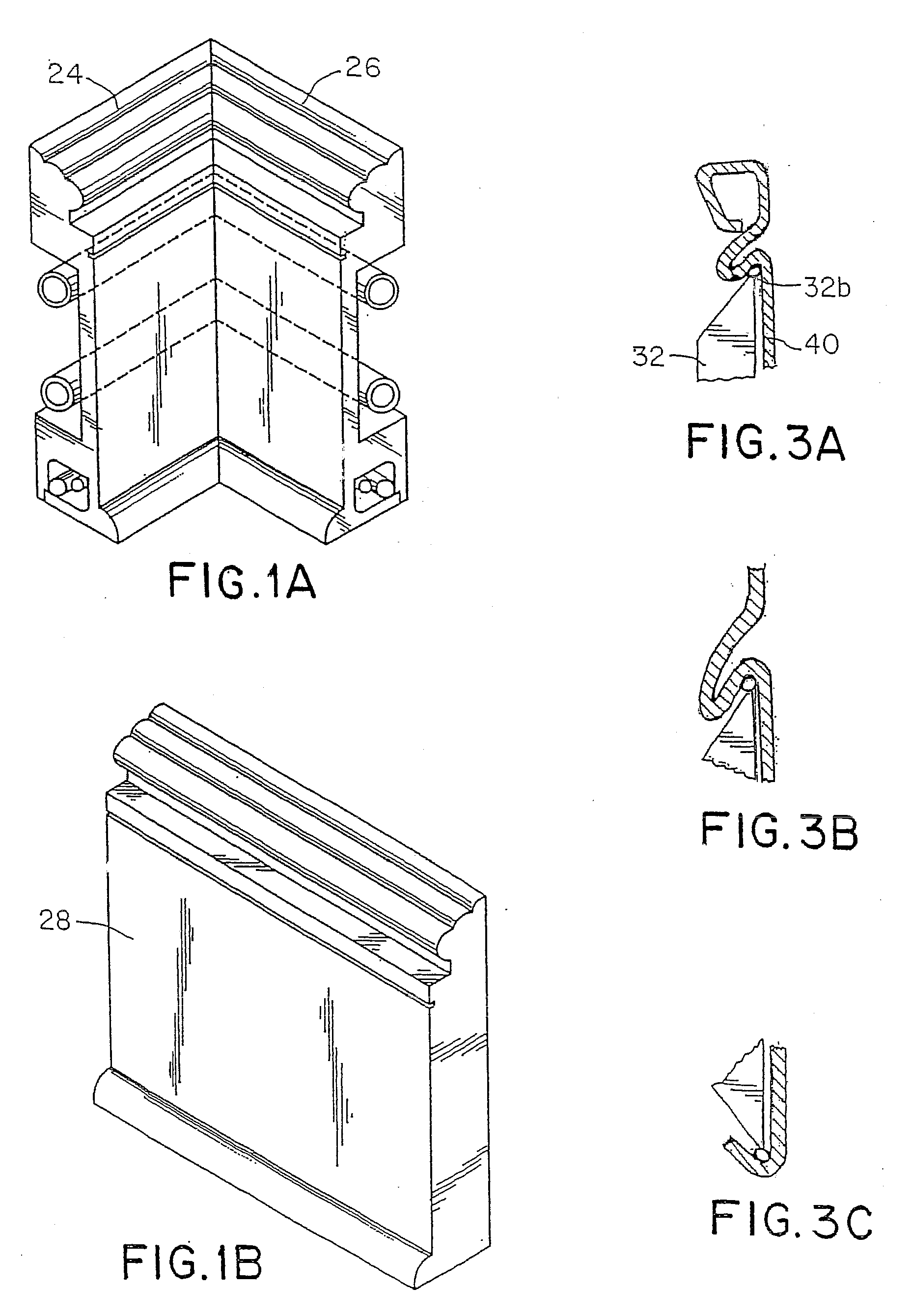
[0053] The baseboard system according to the present invention is generally designated by the reference numeral 20. The system 20 includes, in the example shown in FIG. 1, a baseboard unit 20A on the wall 14, such as below window W, and unit 20B somewhat centered in the middle of wall 16 between the corner 18 of the enclosure, and an opening in the wall, namely, door 19. The baseboard units 20A and 20B are arranged along the walls 14, 16, respectively, proximate to the...


PUM


Abstract

A baseboard system includes baseboard units through which conduits extend carrying heated fluids, and moldings about the free ends of the baseboards, to provide a generally uniform external surface configuration. The moldings are in the nature of conventional moldings made of wood, pressed wood, plastic or the like. The use of the moldings with the baseboards provides an efficient, cost-effective system that produces a uniform appearance and facilitates cleaning.

Description

CROSS REFERENCE TO RELATED APPLICATION [0001] This application is a Continuation-in-Part (CIP) of U.S. patent application Ser. No. 10 / 255,326, issued as U.S. Pat. No. 7,255,152 on Aug. 14, 2007.BACKGROUND OF THE INVENTION [0002] 1. Field of the Invention [0003] This invention generally relates to baseboard heaters, and, more specifically, to an efficient baseboard and molding system that provides sufficient heat exchange with desired heat distribution patterns while providing a substantially continuous profile having a substantially continuous external surface configuration along a selected portion of a wall of an enclosure to be heated. [0004] 2. Description of the Prior Art [0005] Numerous baseboard heaters have been proposed. For example, U.S. Pat. No. 5,597,033 to Cali discloses a functional baseboard panel that includes a heat transfer tube and a non-functional panel. This non-functional panel provides symmetry in the room and allows for expansion if more functional panels are ...

Claims


Application Information

Patent Timeline
Patent Type & Authority Applications(United States)
IPC IPC(8): F24D19/02F24D3/00F24D19/04F28F1/32
CPCF28F1/32F24D19/04
Inventor FRIEDLICH, WILLIAM
Owner FRIEDLICH WILLIAM
Learn More