Image Reading Apparatus and Image Reading Method
a reading apparatus and reading method technology, applied in the direction of optical radiation measurement, printers, instruments, etc., can solve the problem that the output device cannot be specified, and achieve the effect of increasing the read time, increasing the memory consumption, and shrinking the calorimetric error
- Summary
- Abstract
- Description
- Claims
- Application Information
AI Technical Summary
Benefits of technology
Problems solved by technology
Method used
Image
Examples
first embodiment
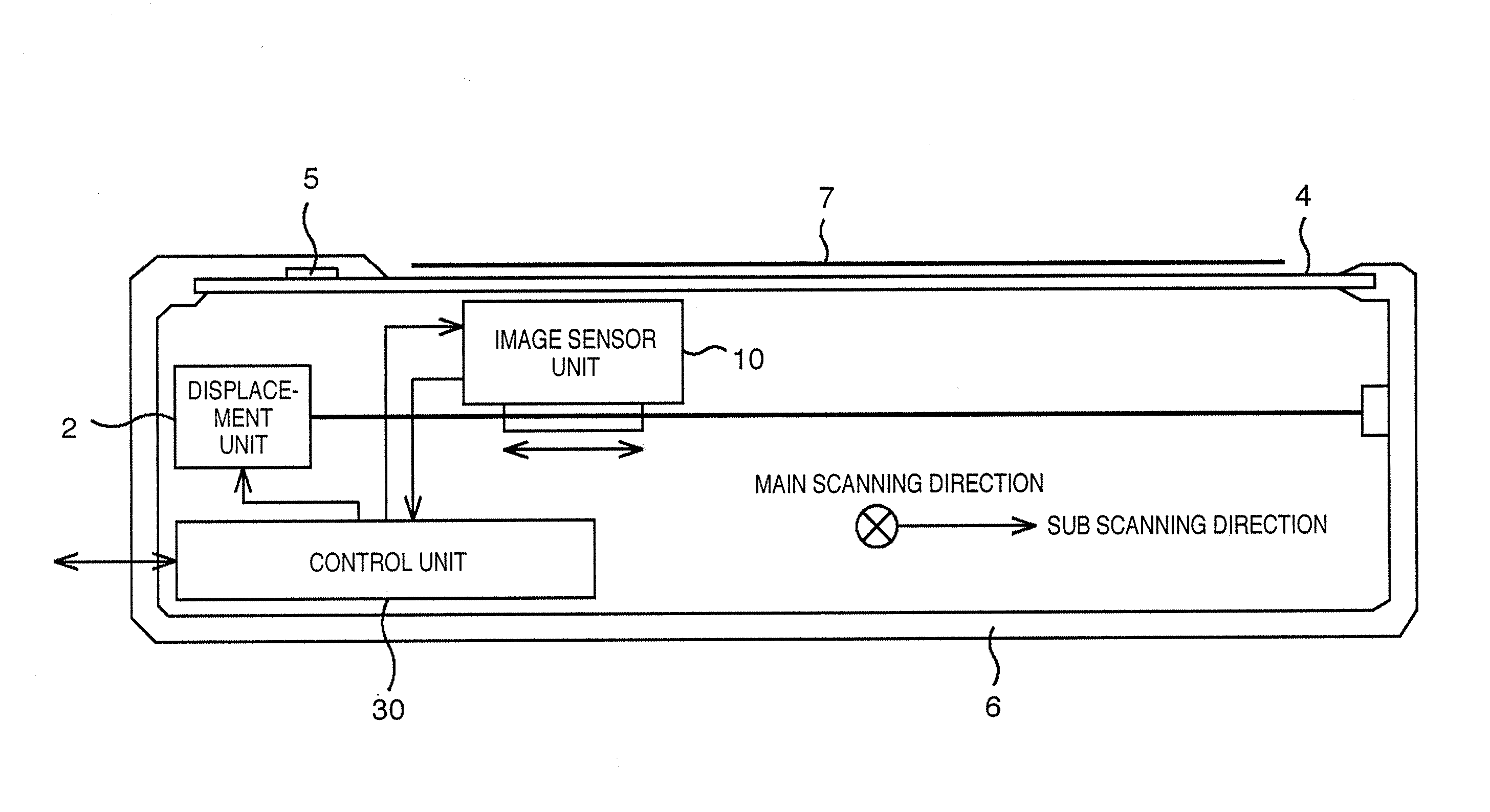
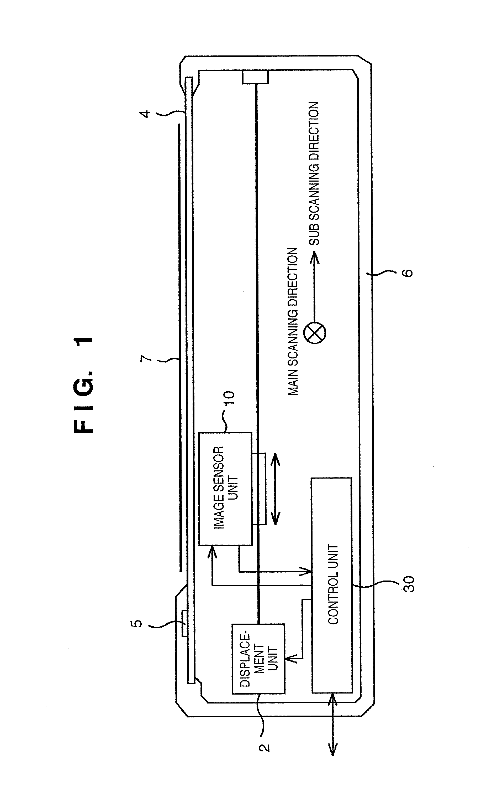
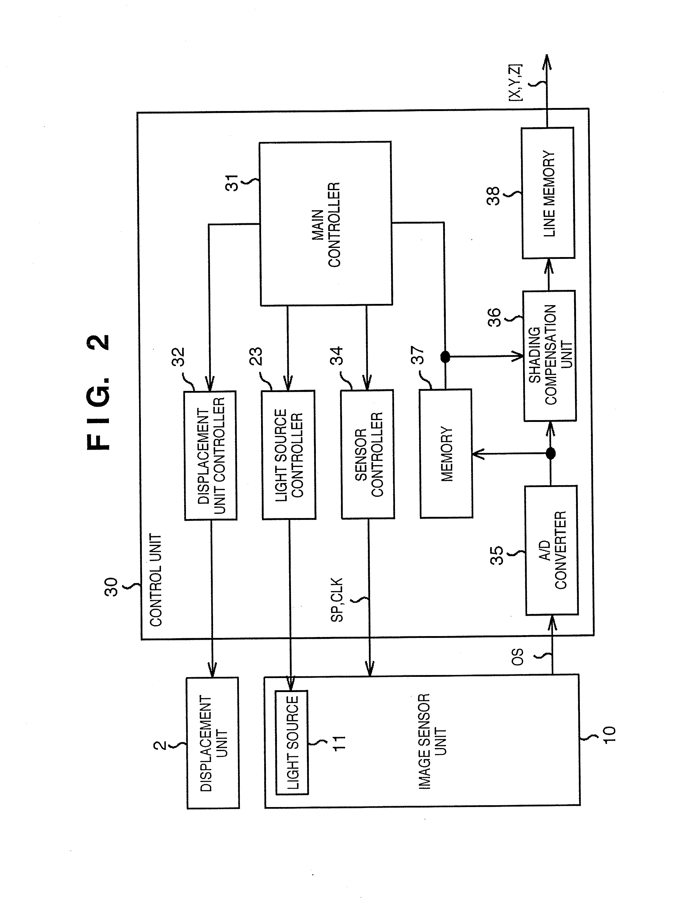
[0077]FIG. 1 depicts an exploded cross-sectional view that describes a sample assembly of an image reading apparatus according to an embodiment of the present invention. An image reading apparatus 6 according to the embodiment has a different image sensor unit and control unit assembly from that of the conventional image reading apparatus shown in FIG. 19. Accordingly, components of the image reading apparatus 6 that are identical to the conventional image reading apparatus will be marked with symbols identical to the symbols shown in FIGS. 8 through 19, and detailed descriptions thereof will be omitted.
(Image Reading Apparatus Assembly)
[0078] The image reading apparatus 6 according to the embodiment is capable of being used for scanning, color facsimile, or as a multi-function peripheral thereof, as well as an image input component of a color copier. The description according to the embodiment will cite an example of an image reading apparatus comprising an image sensor unit 10,...
modified example
[0109] It is possible, as another method of deriving the emission proportion of the five LEDs 11a through 11e, to employ the simplified method depicted below, in a case that the respective emission spectra of each of the LEDs 11a through 11e is known.
[0110] For example, if the dominant emission wavelength of the five LEDs 11a through 11e are presumed to be α, β, γ, δ, and ε, respectively, all in nm, then the mixed proportion of the LEDs 11a through 11e that is equivalent to the color-matching function x(λ) is configured to be x(α):x(β):x(γ):x(δ):x(ε), the mixed proportion of the LEDs 11a through 11e that is equivalent to the color-matching function y(λ) is configured to be y(α):y(β):y(γ):y(δ):y(ε), and the mixed proportion of the LEDs 11a through 11e that is equivalent to the color-matching function z(λ) is configured to be z(α):z(β):z(γ):z(δ):z(ε). Consequently, it is possible to make a rough approximation of the color-matching functions x(λ), y(λ), and z(λ), by taking a composite...
second embodiment
[0116] Following is a description of a second embodiment, which differs from the first embodiment only in the timing by which the LEDs 11a through 11e are turned on. Accordingly, the description of the second embodiment will use symbols identical to the symbols given in FIGS. 1 through 6, and FIGS. 8 through 19, and omit detailed description, for the components that are identical to components in the conventional image reading apparatus, as well as the image reading apparatus 6 according to the first embodiment.
[0117] Given that the sensor array 15 that constitutes the image sensor unit 10 integrates and outputs an optical carrier signal throughout one cycle, it is permissible for the photoelectric conversion function of the sensor array 15 to be performed in any of the respective image signal accumulation cycles TS1, TS2, or TS3. It would be permissible, for example, to turn on the light source 11 in a time-shared manner.
[0118]FIG. 7 is a timing chart explaining an example of a d...
PUM
 Abstract
Description
Claims
Application Information
 - R&D
- Intellectual Property
- Life Sciences
- Materials
- Tech Scout
- Unparalleled Data Quality
- Higher Quality Content
- 60% Fewer Hallucinations
Browse by: Latest US Patents, China's latest patents, Technical Efficacy Thesaurus, Application Domain, Technology Topic, Popular Technical Reports.
© 2025 PatSnap. All rights reserved.Legal|Privacy policy|Modern Slavery Act Transparency Statement|Sitemap|About US| Contact US: help@patsnap.com


