

Atenna device
a technology of antenna device and ferromagnetic core, which is applied in the direction of anti-theft device, loop antenna with ferromagnetic core, transportation and packaging, etc., can solve the problems of increasing the types of antenna device, requiring many components, and complication in manufacturing
- Summary
- Abstract
- Description
- Claims
- Application Information
AI Technical Summary
Problems solved by technology
Method used
Image

Examples
Embodiment Construction
[0026]The present invention provides an antenna device that solves conventional problems as described above, does away with the wiring section, and is easy to manufacture.
[0027]Referring now to FIG. 1 to FIG. 4D, description will be given in the following on preferred embodiments of the present invention.
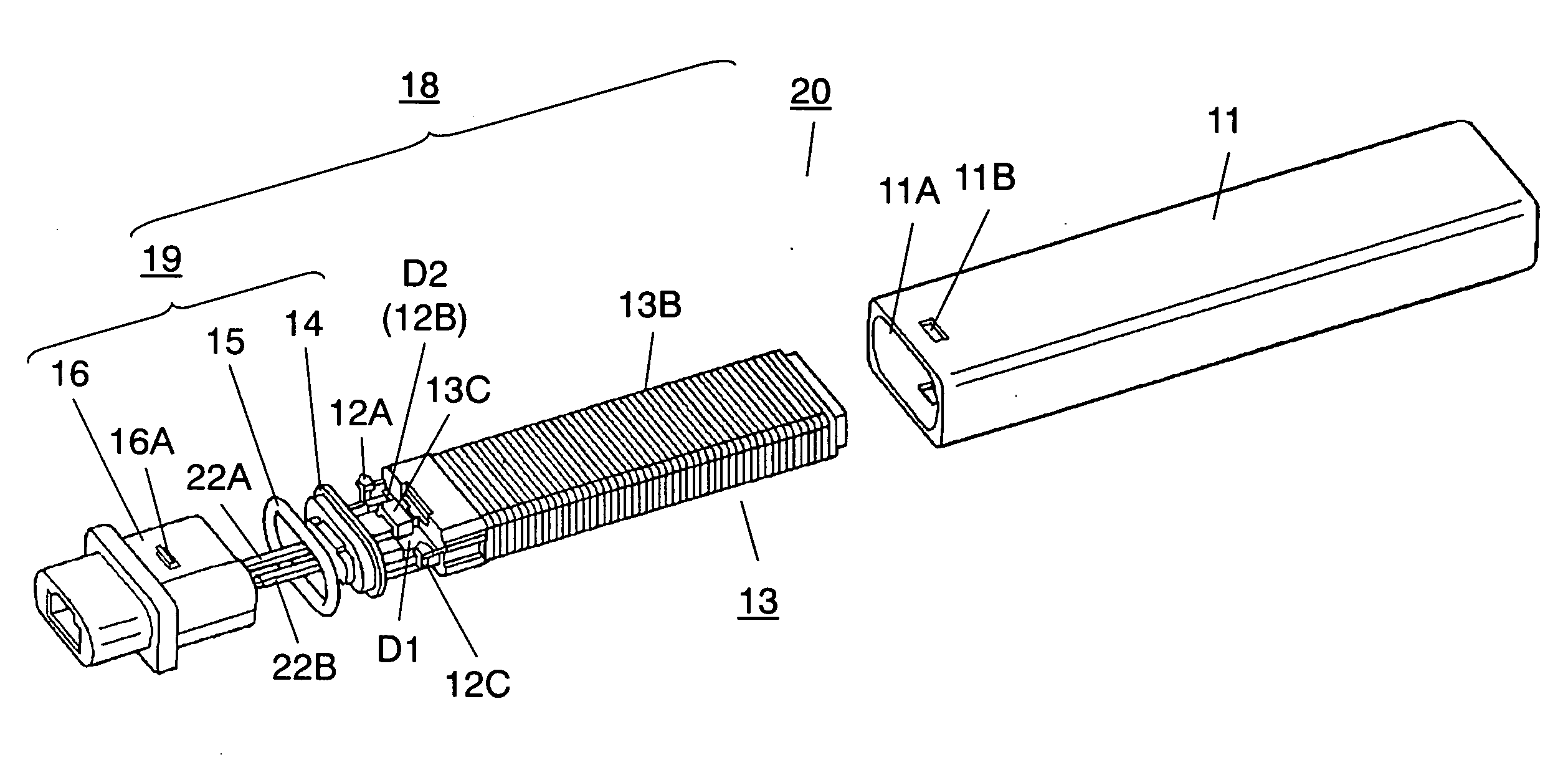
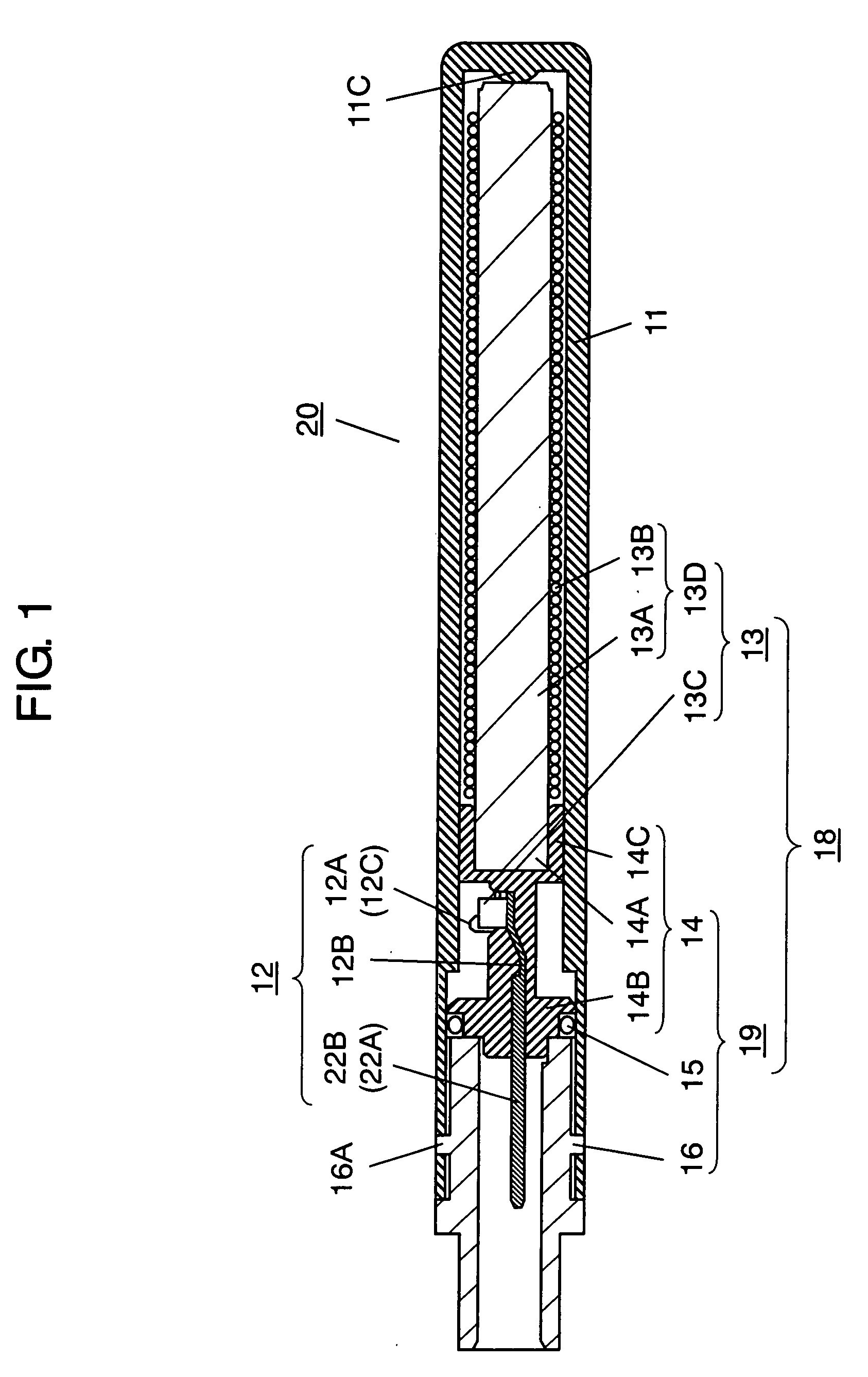
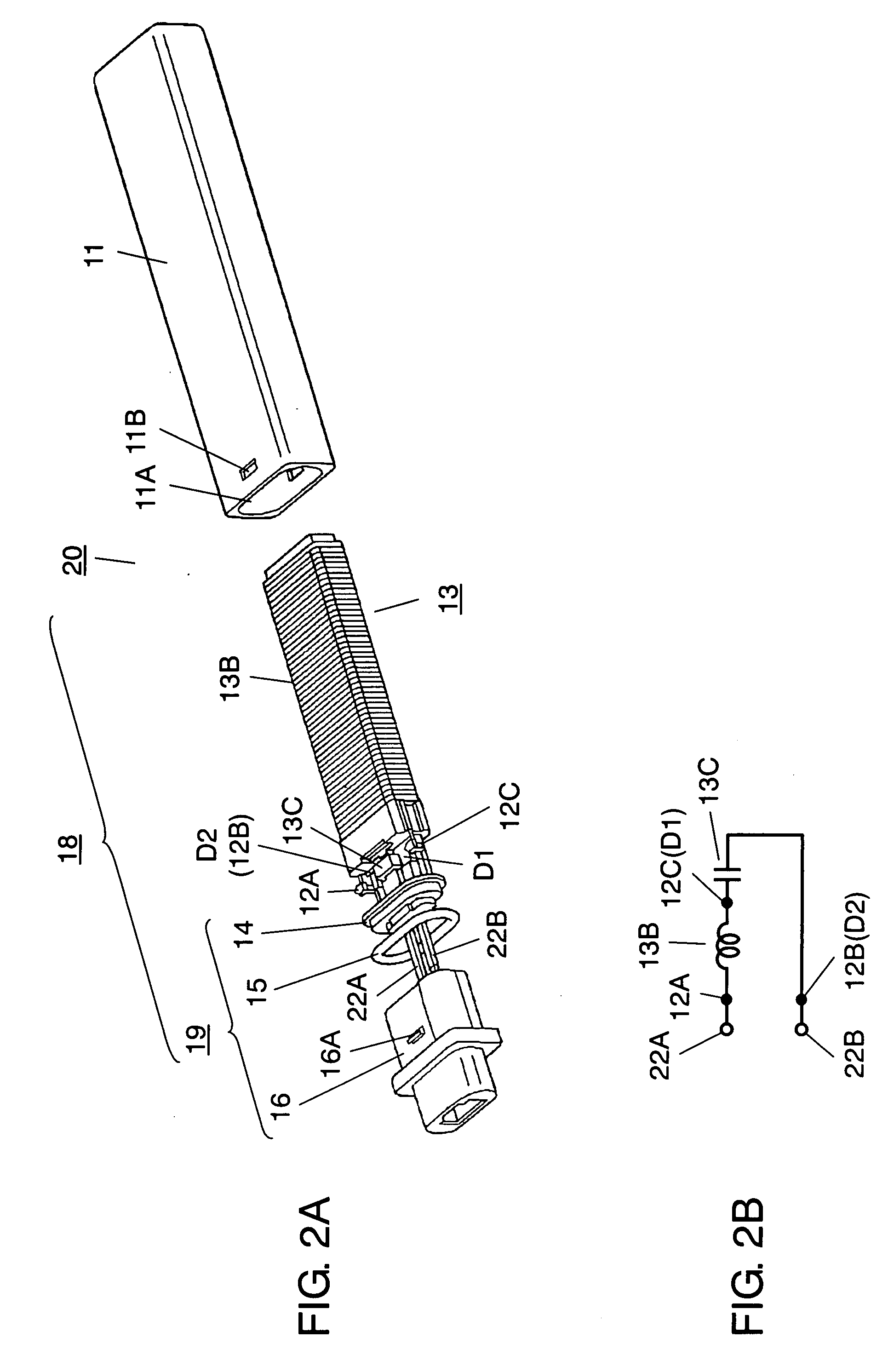
[0028]FIG. 1 is a sectional view of an antenna device in a preferred embodiment of the present invention. FIG. 2A is an exploded perspective view of the antenna device. FIG. 2B is an equivalent circuit diagram of the antenna device. In these figures, nearly tubular case 11 is made of a heat-resistant and mechanically strong material such as polybutylene terephthalate (PBT). Opening 11A is provided on the left side face of case 11.
[0029]Antenna member 13 is mainly formed with rod-like core 13A made of a magnetic material such as ferrite, coil 13B wound on its outer periphery, and capacitor 13C connected in series with coil 13B.
[0030]Furthermore, core section 13D, being an integrated ...
PUM
 Abstract
Description
Claims
Application Information