Intervertebral Spacer for Cervical Vertebrae

a technology for cervical vertebrae and spacers, applied in the field of intervertebral spacers, can solve the problems of inability to use cervical vertebrae, inability to install spacers between, and damage to the intervertebral disk, and achieve the effect of limiting the relative displacement of said vertebra

Inactive Publication Date: 2008-02-07
ZIMMER SPINE INC
View PDF3 Cites 52 Cited by
  • Summary
  • Abstract
  • Description
  • Claims
  • Application Information

AI Technical Summary

Benefits of technology

The invention provides an intervertebral spacer that can be used between two adjacent cervical vertebrae to limit their displacement.

Problems solved by technology

The present invention relates to an intervertebral spacer for inserting between two adjacent cervical vertebrae and a set of intervertebral spacers comprising two of the above-specified types. The technical problem addressed by the invention is the need for a spacer that can be used in the cervical region of the spine, which has a convex shape in the anterior direction and is more complex in its movements than the dorsal or lumbar region. Existing spacers designed for the dorsal or lumbar region cannot be used in the cervical region because of the close proximity of the spinous processes of the vertebrae.

Method used


Image

  • Intervertebral Spacer for Cervical Vertebrae
  • Intervertebral Spacer for Cervical Vertebrae
  • Intervertebral Spacer for Cervical Vertebrae

Examples


first embodiment

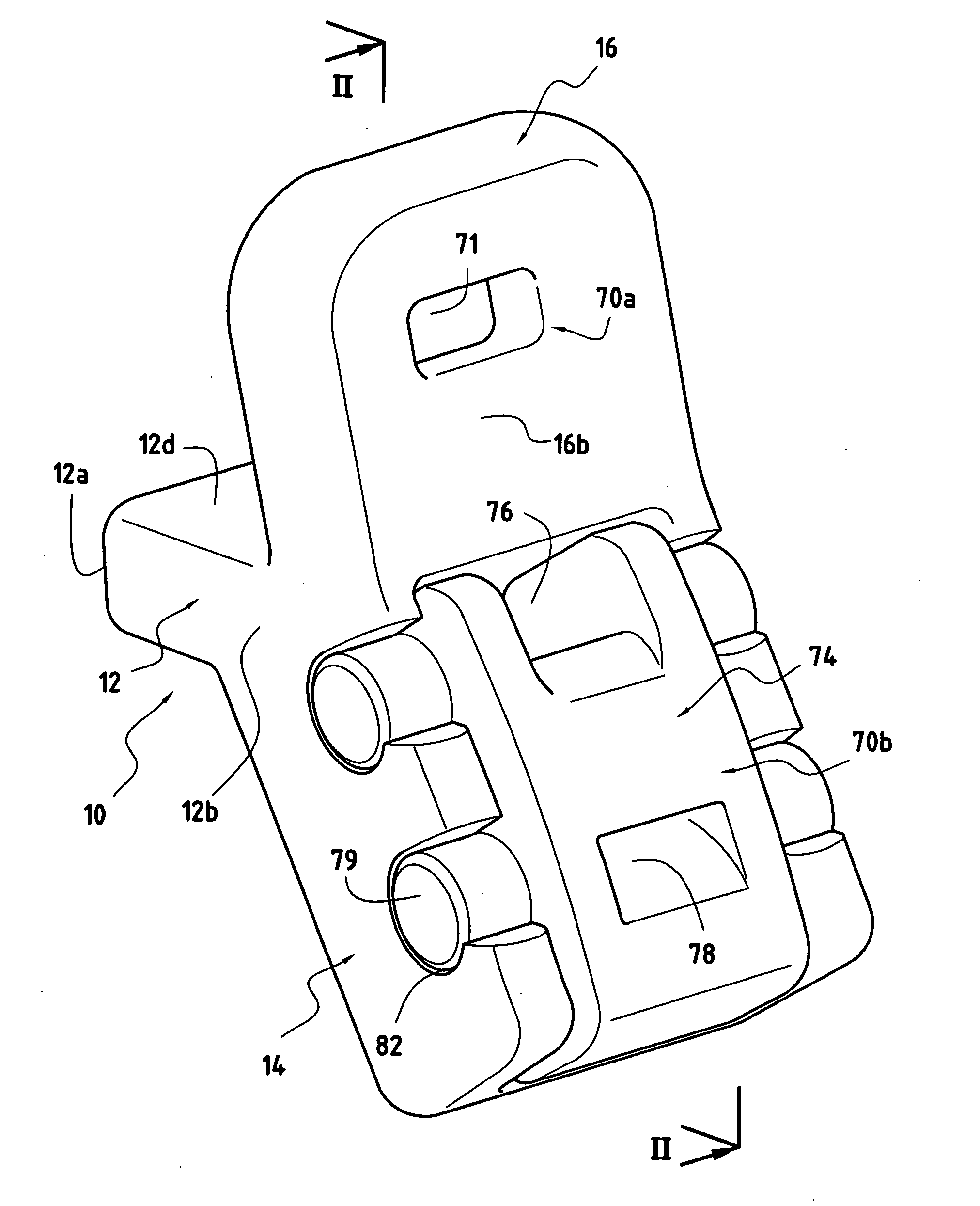
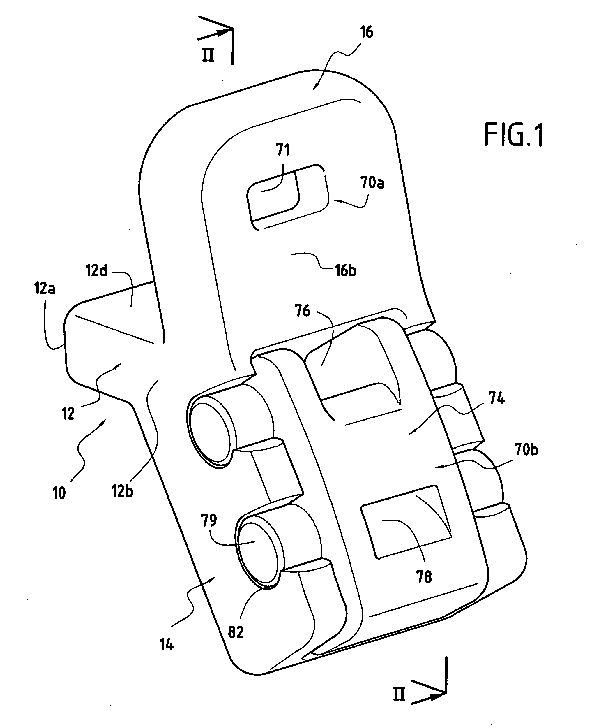
[0032] In the invention, and with reference to FIGS. 1, 2, and 2A, the spacer comprises a spacer body 10, itself comprising a spacer part 12 having a distal first end 12a and a proximal second end 12b from which there extend above and below the part 12, a top flange 16 and a bottom flange 14. Each flange 14 and 16 presents a respective anterior face 14a, 16a facing in the same direction as the spacer part 12, and a posterior face 14b, 16b opposite from the corresponding anterior face.

[0033] The spacer body 10 is symmetrical about its midplane II-II shown in FIG. 1, which plane is parallel to the direction in which distance is measured between the distal end 12a and the proximal end 12b of the spacer part 12.

[0034] The spacer part 12 of the spacer body 10 is for insertion between two cervical vertebrae, an upper vertebra V2 and a lower vertebra V1. In the example shown, the part 12 presents opposite top and bottom faces 12d and 12c that are substantially parallel to each other. The ...

second embodiment

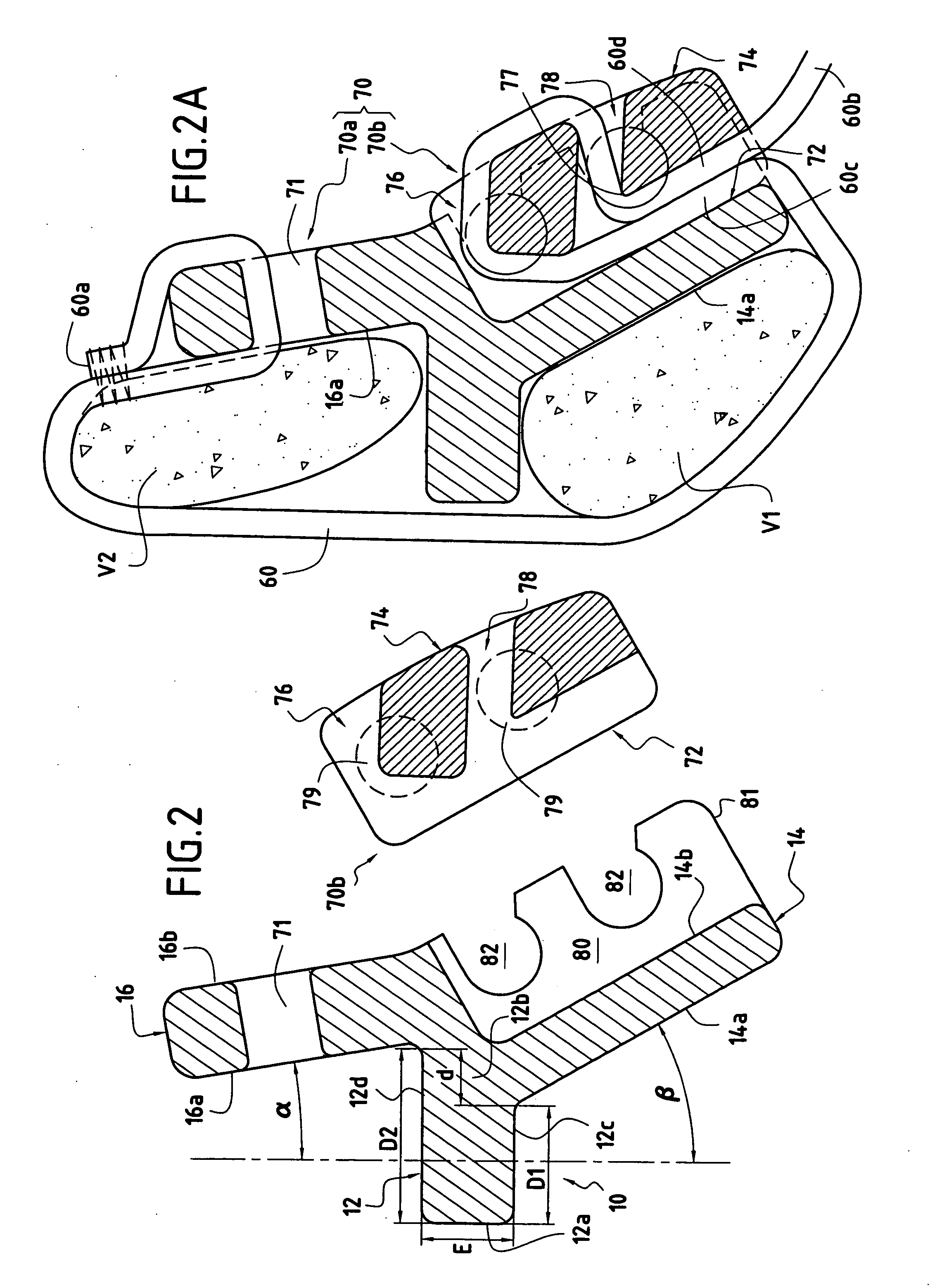
[0048]FIGS. 3, 3A, 4, and 5 show a spacer of the invention.

[0049] This spacer comprises a spacer body 10 substantially identical to that described above. That is why those portions of the spacer body in FIGS. 3 to 5 that are analogous to portions of the spacer body in FIGS. 1 and 2 are given the same reference numerals. The major difference between the two spacer bodies lies in the fact that in the second embodiment the posterior faces 16a and 14a of the top and bottom flanges 16 and 14 are coplanar.

[0050] In contrast, in this second embodiment, the spacer has retention means 150 for retaining the spacer body 10 in position against the vertebrae V1 and V2 that are different from the spacer means 50 described above.

[0051] The spacer means 150 comprise a strap 160 presenting two ends 160a and 160b, and self-blocking fastener means 170 enabling the two ends 160a and 160b to be secured to the spacer body 10. These self-blocking fastener means 170 extend over the posterior faces 16b an...


PUM


Abstract

An intervertebral spacer for placing between two adjacent, upper and lower cervical vertebrae, the spacer being characterized in that it comprises a spacer body and retention means for retaining the spacer body in position against said vertebrae, the retention means comprising a strap and fastener means that are removable and self-blocking, enabling the ends of the strap to be secured to the spacer body, said spacer body comprising: a spacer part having two opposite ends, a portion of the first end being suitable for being inserted between said vertebrae; and top and bottom flanges connected via their bases to the second end of the spacer part and extending on either side thereof, each flange presenting an anterior face facing towards the spacer part and suitable for coming to bear against the posterior portion of the lamina of the upper or lower vertebra.

Description


Claims


Application Information

Patent Timeline
Owner ZIMMER SPINE INC
Why Eureka
Try Eureka