
Refrigeration Control System in Combined Refrigeration Appliances

a refrigeration appliance and control system technology, applied in refrigerators/freezers, domestic cooling devices, lighting and heating devices, etc., can solve the problems of limited design adjustment and unwound operation, and achieve the effect of minimizing the occurrence of activation of the refrigerating compartment fan

Inactive Publication Date: 2008-02-14
WHIRPOOL SA
View PDF5 Cites 24 Cited by
  • Summary
  • Abstract
  • Description
  • Claims
  • Application Information

AI Technical Summary

Benefits of technology

[0005] As a function of the inconveniences mentioned above, it is an object of the present invention to provide a refrigeration control system in combined refrigeration appliances of the type considered herein, which leads to a synchronized operation of the fans of the refrigerating and freezing compartments, in order to minimize the occurrences of activation of the refrigerating compartment fan while the compressor fan is deactivated.
[0006] It is a further object of the present invention to provide a refrigeration control system as described above, which allows the user to set the operation of the compressor and of the fans to a special reduced and temporary usage pattern of the combined refrigeration appliance.
[0007] It is still a further object of the present invention to provide a refrigeration control system as described above, which allows the user to set the operation and the speed of the refrigerating compartment fan to a special intense and temporary usage pattern of the refrigerating compartment. SUMMARY OF THE INVENTION
[0012] The control means of the present invention further allows the user to instruct the refrigeration appliance to operate in a “vacation mode”, according to which the operational temperature ranges of the refrigerating and freezing compartments are reduced to a less cool condition and the speeds of the refrigerating compartment and freezing compartment fans are set to constant low values.

Problems solved by technology

Nevertheless, in terms of reduction of energy consumption, the above operation is not desired, since it causes irregular operating cycles of the compressor.
Another aspect regarding the known refrigeration control systems is the fact that they do not allow the occurrence of a joint operation of the compressor and fans which is adequate to a special and temporary usage pattern of the refrigeration appliance as a whole or of the refrigerating compartment only.
In the known appliances, the designed adjustment is limited to the setting of the operational temperature ranges of the refrigeration appliance.

Method used


Image

  • Refrigeration Control System in Combined Refrigeration Appliances
  • Refrigeration Control System in Combined Refrigeration Appliances
  • Refrigeration Control System in Combined Refrigeration Appliances

Examples


Embodiment Construction

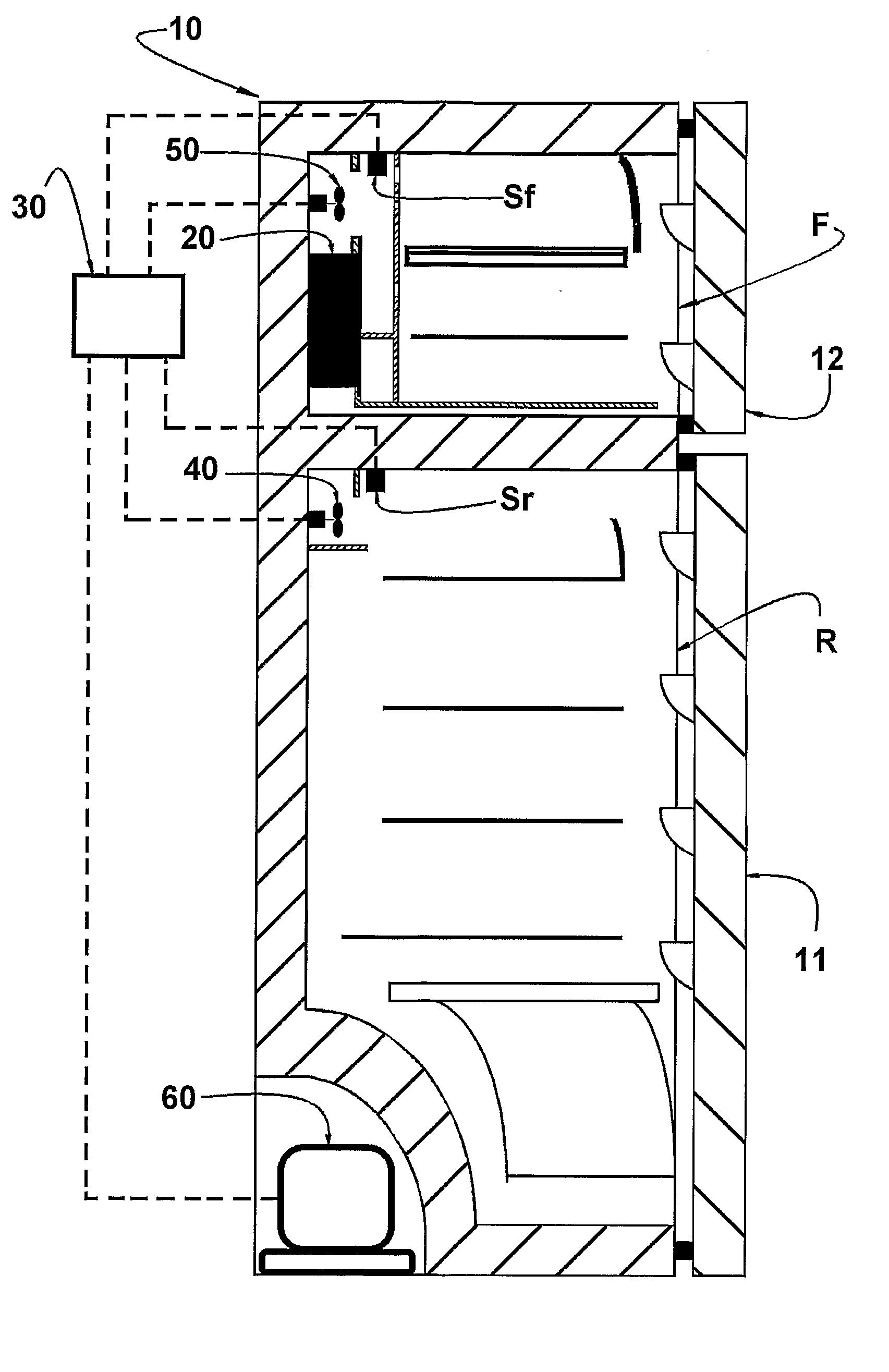
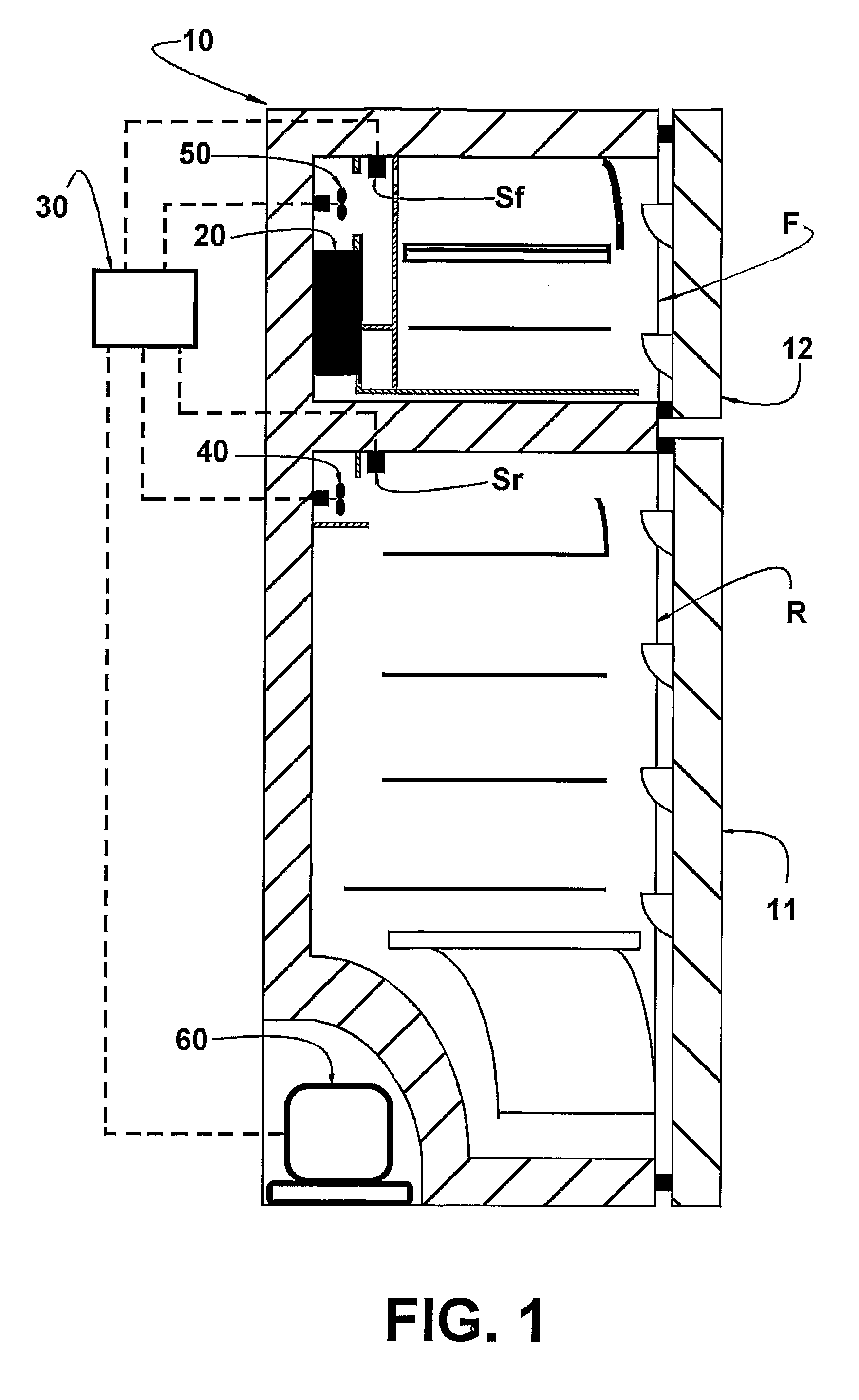
[0017] As mentioned above, the present refrigeration control system is applied to a combined refrigeration appliance whose cabinet 10 defines, internally, a refrigerating compartment R and a freezing compartment F which are respectively closed by front doors 11, 12. In the interior of at least one of the refrigerating compartment R and freezing compartment F is provided an evaporator 20 which in the illustrated embodiment is positioned in the internal rear region of the freezing compartment F. The refrigerating compartment R is provided with a refrigerating compartment temperature sensor Sr and the freezing compartment with a freezing compartment temperature sensor Sf, said temperature sensors being operatively associated with a control means 30 adequately secured to the cabinet 10 usually in the lower rear portion of the latter.

[0018] Cabinet 10 further houses a refrigerating compartment fan 40 and a freezing compartment fan 50 which are positioned and dimensioned to produce respe...


PUM


Abstract

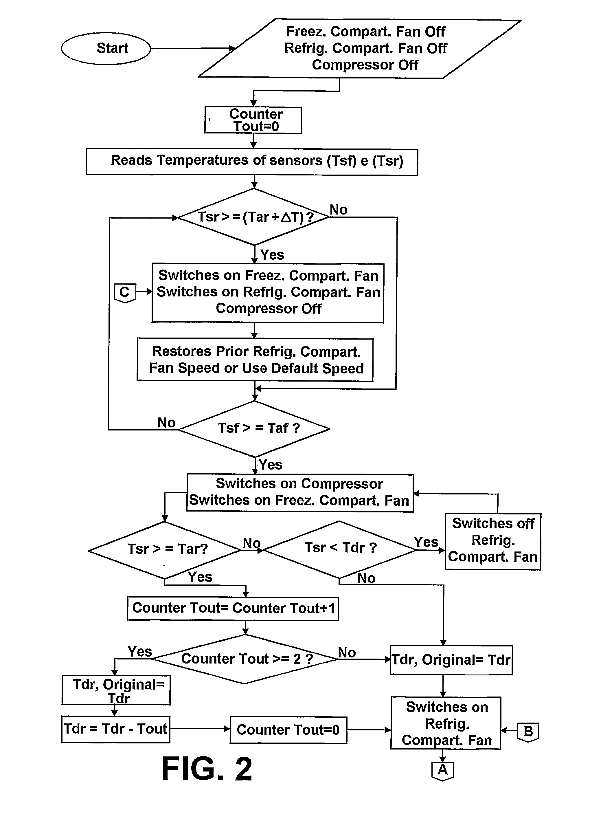
A refrigeration control system in combined refrigeration appliances of the type comprising: a refrigerating compartment; a freezing compartment; a compressor; an evaporator; a refrigerating compartment fan and a freezing compartment fan; and a control means to activate and deactivate the compressor and both the refrigerating compartment fan and the freezing compartment fan as a function of the activation and deactivation temperatures detected by the refrigerating compartment temperature sensor and the freezing compartment temperature sensor. The control means is operatively associated with the refrigerating compartment fan to selectively and periodically adjust the speed of the latter, so that the temperature of the refrigerating compartment reaches a deactivation value of the refrigerating compartment fan at the same time in which the temperature of the freezing compartment reaches a deactivation value of both the freezing compartment fan and the compressor.

Description

FIELD OF THE INVENTION [0001] The present invention refers to a refrigeration control system to be applied to combined refrigeration appliances that present a refrigerating compartment and a freezing compartment, each provided with a forced air flow which is refrigerated in an evaporator and blown by a respective fan. PRIOR ART [0002] There are well known in the art the combined refrigeration appliances in which each of the refrigerating and freezing compartments is provided with a temperature sensor operatively associated with an electronic control module or means which is designed to command the activation of the fans of said compartments and of the compressor of the refrigeration circuit of the refrigeration appliance. In said combined appliances, the refrigerating compartment temperature sensor informs the control means about the activation and deactivation temperatures of the refrigerating compartment fan, in order to vary the cool air supply to the compartment as a function of...

Claims


Application Information

Patent Timeline
IPC IPC(8): F25D17/00F25D17/06F25D29/00
CPCF25B2600/0251F25B2600/112F25D17/065F25D29/00Y02B40/32F25D2400/04F25D2700/12F25D2700/122F25D2317/0682Y02B40/00
Inventor PIMENTEL, FABIO RIBEIROMEZAVILA, MOACYR MARANGONESCHMID, ALEXANDRE CURYRODRIGUES, ROGERIO JR.REBELLO RUCKER, ALEXANDRE PINTOMARQUES, MARCO EDUARDO
Owner WHIRPOOL SA
Learn More