Automatic Balancing Device

a technology of automatic balancing and balancing body, which is applied in the direction of washing machines, applications, washing machines, etc., can solve the problems of affecting the effect of mass, exacerbate the excursion of the rotating body, and inability to achieve the effect of mass in some cases

Inactive Publication Date: 2008-02-14
DYSON TECH LTD
View PDF8 Cites 2 Cited by
  • Summary
  • Abstract
  • Description
  • Claims
  • Application Information

AI Technical Summary

Benefits of technology

[0004] An object of the invention is to provide an automatic balancing system in which the counterbalancing masses are able to provide at least partial counterbalancing at sub-critical speeds but are also free to provide a full counterbalancing effect at speeds above the critical speed. It is a further object of the invention to provide an automatic balancing system by means of which the maximum excursion of the rotating body is minimised reliably and simply.

Problems solved by technology

It has also been recognised that, if these counterbalancing masses are left unconstrained at speeds below the critical speed, they exacerbate the excursion of the rotating body which is highly undesirable.
This system has merit but suffers from the disadvantage that the amount of counterbalancing achievable below the critical speed varies with time and so the point at which the speed of rotation is increased to and through the critical speed needs to be carefully controlled in order to achieve the best results.
The fact that the same constraints are applied to the counterbalancing masses at speeds both above and below critical can also inhibit the effect of the masses in some cases.

Method used


Image

  • Automatic Balancing Device
  • Automatic Balancing Device
  • Automatic Balancing Device

Examples


fourth embodiment

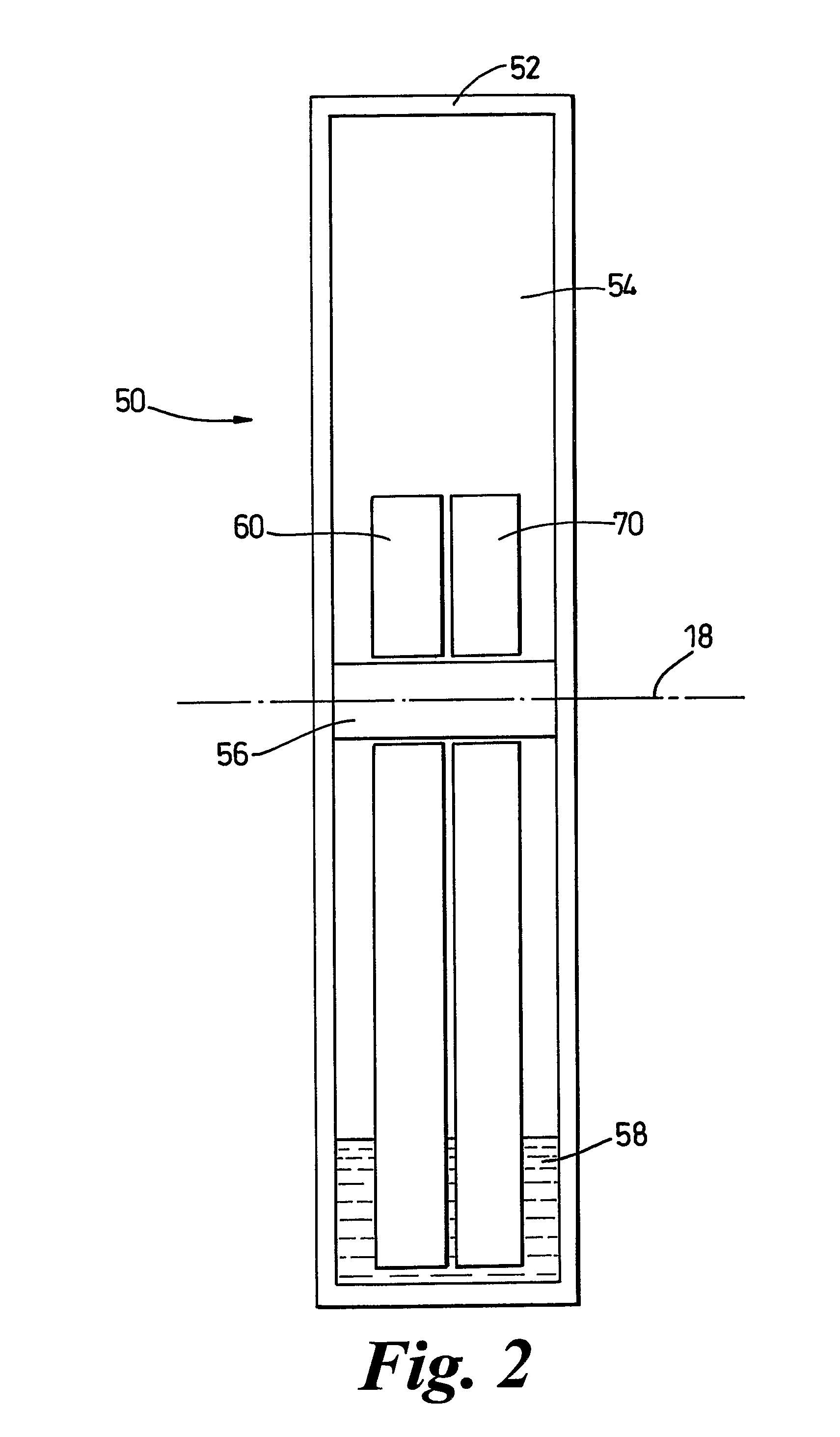
[0072] the invention is illustrated in FIG. 12. In this embodiment, the automatic balancing device 250 comprises two separate, annular ballraces 260, 270 which are arranged to be concentric with the axis 218 about which the drum, or other rotating body in which the out-of-balance mass to be counterbalanced is located, rotates. The first ballrace 260 is of the type which is known in the art. It comprises an annular race 262 in which a plurality of identical balancing balls 264 are located. A viscous fluid such as oil (not shown) provides viscous coupling between the wall of the race 262 and the balls 264. The balls 264 are dimensioned so that, when they lie adjacent one another, they occupy less than half of the race 262 so as to maximize their balancing effect. A mechanism (not shown), which is operative at speeds below the critical speed of the system in which the device 250 is used, is provided for fixing the balls 264 at equispaced positions around the race 262. When the balls 26...

fifth embodiment

[0078] The previously described embodiments are all primarily suitable for use with bodies which rotate about a horizontal (or substantially horizontal) axis, although they could also be used in machines having a substantially vertical axis. The fifth embodiment, which is illustrated in FIGS. 13a, 13b, 14a and 14b, is however well suited for use with a body which rotates about a vertical (or substantially vertical) axis. In the embodiment, the device 350 consists of a support surface 360 which is mounted concentrically with the axis 318 about which the body in which the out-of-balance mass to be counterbalanced is present. The support surface 360 comprises a circular central portion 362 surrounded by a cylindrical lip 364. An inclined portion 366 extends upwardly and outwardly from the upper edge of the lip 364 to a cylindrical wall 368 and an overhanging lip 370. The uppermost part of the inclined portion, the cylindrical wall 368 and the overhanging lip 370 combine to form an annu...

sixth embodiment

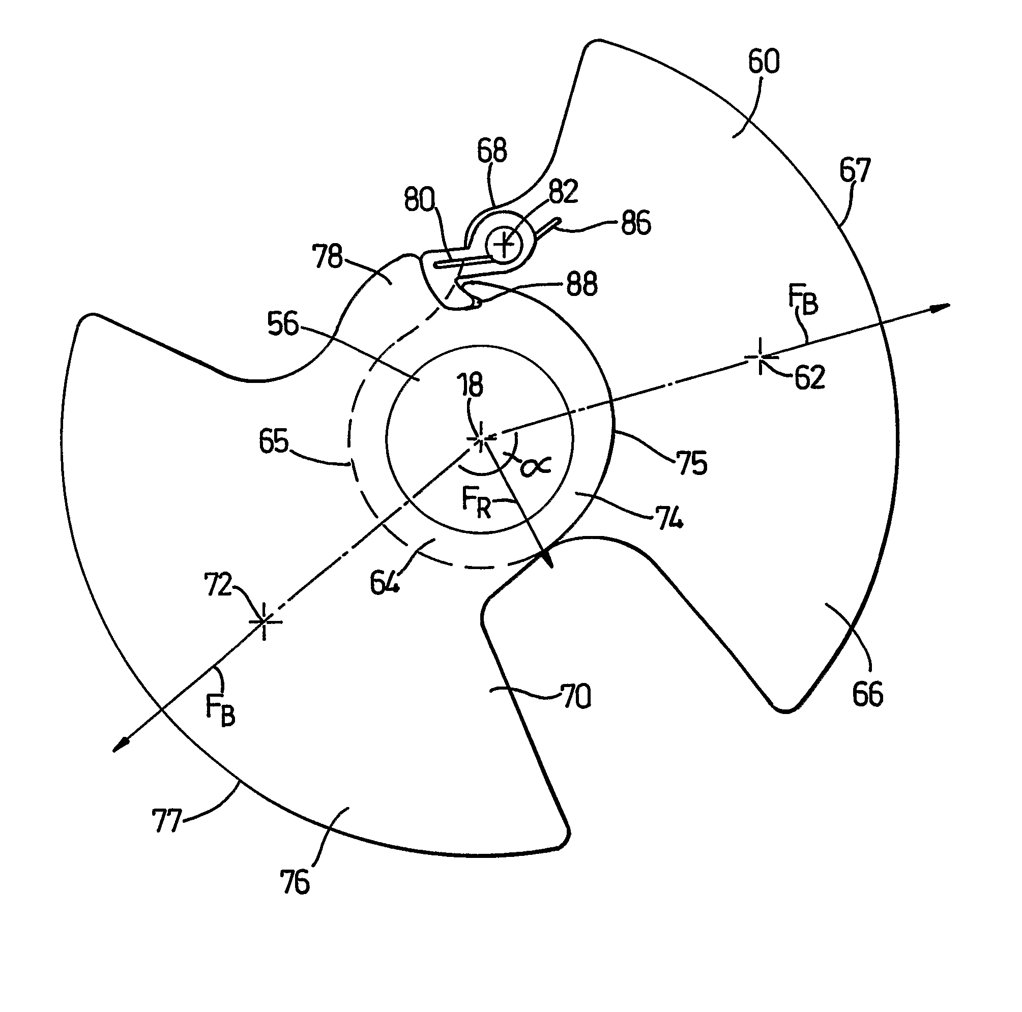
[0086] the invention is shown in FIGS. 15a to 15c. In this embodiment, the automatic balancing device 450 again comprises a wall 452 which defines a cylindrical chamber 454. A viscous fluid (not shown) is provided in the chamber 454 to provide viscous coupling between the wall 452 and the counterbalancing masses 460, 470. The counterbalancing masses 460, 470 are supported next to one another on an axle 456 so as to be freely rotatable about the axis 458, which is concentric with the drum of the washing machine or other dynamic system in which the device 450 is used.

[0087] At speeds below the critical speed, the counterbalancing masses 460, 470 are restrained so that a non-zero resultant balancing force FR, which is freely movable about the axis 458, is produced. This is achieved by the provision of a catch 474 on the counterbalancing mass 470 which, at speeds below the critical speed, is received by a notch 464 on the other counterbalancing mass 460. The catch 474 is shown located i...


PUM

PropertyMeasurementUnit
angleaaaaaaaaaa
angleaaaaaaaaaa
angleaaaaaaaaaa

Abstract

An automatic balancing device for counterbalancing an out-of-balance mass includes a plurality of counterbalancing masses, each of which is movable in a circular path about the axis so as to generate a balancing force. The balancing forces combine to produce a resultant balancing force which varies between minimum and maximum values. At a first speed of rotation of the body about the axis, the movement of at least one of the counterbalancing masses is restrained so that a substantially constant, non-zero resultant balancing force is produced, the resultant balancing force being freely movable about the axis. At a second speed of rotation of the body about the axis, the counterbalancing masses are free to adopt a position in which the out-of-balance mass is counterbalanced. The device allows at least partial counterbalancing of the out-of-balance mass at speeds below the critical speed of the system in which it is used.

Description

REFERENCE TO RELATED APPLICATIONS [0001] This application is a national stage application under 35 USC 371 of International Application No. PCT / GB2005 / 004301, filed Nov. 7, 2005, which claims the priority of United Kingdom Application No. 0425313.4, filed Nov. 17, 2004, the contents of both of which prior applications are incorporated herein by reference.FIELD OF THE INVENTION [0002] The invention relates to an automatic balancing device for counterbalancing an out-of-balance mass present in a body which is rotatable about an axis. Particularly, but not exclusively, the invention relates to an automatic balancing device which is suitable for use in a washing machine for counterbalancing out-of-balance masses in washing machines during washing and spinning cycles. BACKGROUND OF THE INVENTION [0003] Automatic balancing devices for counterbalancing out-of-balance masses in rotating bodies are known. Many work on the well-known principle that, at speeds above the critical speed of the s...

Claims


Application Information

Patent Timeline
Patent Type & Authority Applications(United States)
IPC IPC(8): D06F37/22D06F37/24
CPCD06F37/225Y10T74/2109D06F37/245F16F15/36F16F15/16
Inventor JONES, DAVID MICHAELHARRISON, MATTHEW DAMIANWILSON, MATTHEW CHARLES EDWARD
Owner DYSON TECH LTD
Why Eureka
Try Eureka