Gas sensor

a technology of gas sensor and spring element, which is applied in the field of gas sensor, can solve the problems of poor contact of the sensor element, damage to the contact element, damage to the spring element, etc., and achieve the effect of facilitating the alignment of the spring elemen

Inactive Publication Date: 2005-11-10
ROBERT BOSCH GMBH
View PDF3 Cites 0 Cited by
  • Summary
  • Abstract
  • Description
  • Claims
  • Application Information

AI Technical Summary

Benefits of technology

[0012] Simple alignment of the spring element during assembly is made possible by the fact that the outside of the spring element has a flat design in the area of the groove and that the spring element's flat area stan

Problems solved by technology

It is disadvantageous in such gas sensors that the spring element has a comparatively steep characteristic curve of spring so that, even through small manufacturing fluctuations, either the force exerted by the spring element is too small, resulting in a poor contact of the sensor element, or a contact element is damaged when the spring element is attached.
It

Method used


Image

  • Gas sensor
  • Gas sensor
  • Gas sensor

Examples


Embodiment Construction

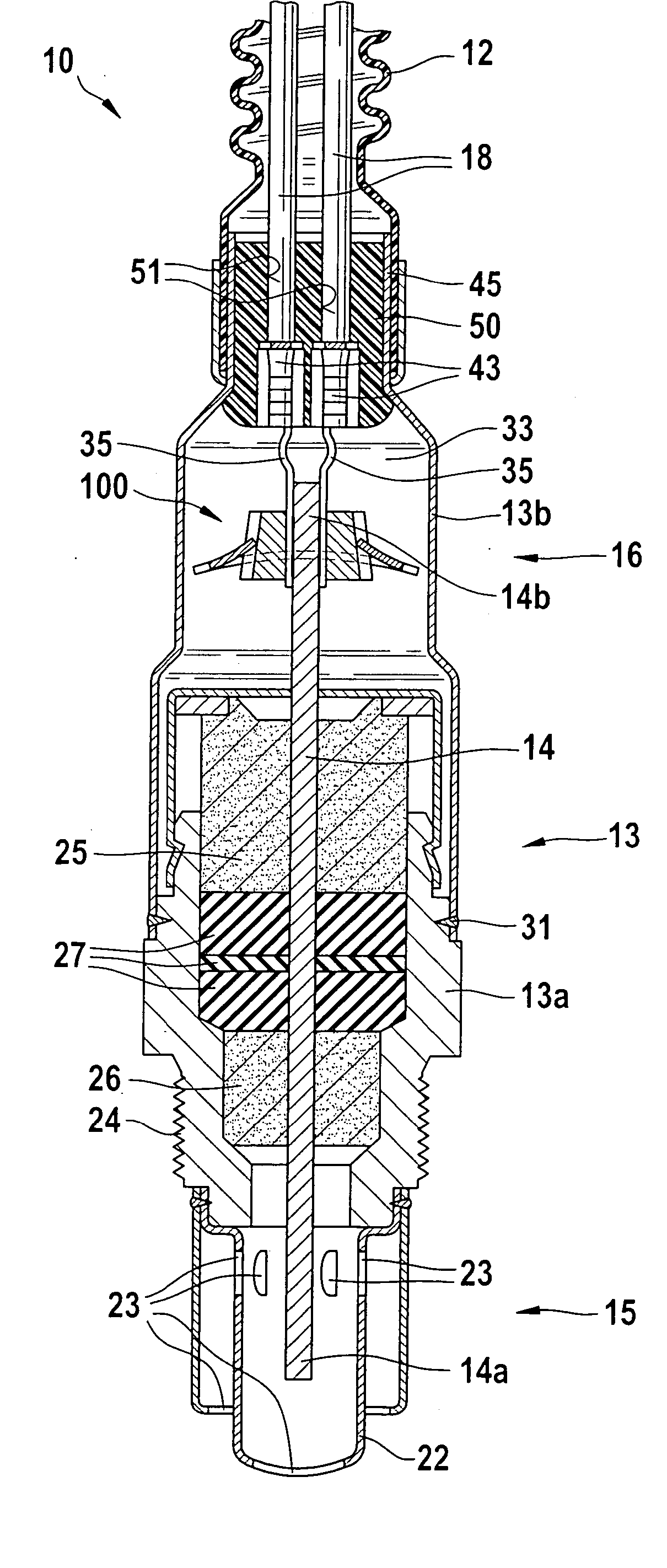
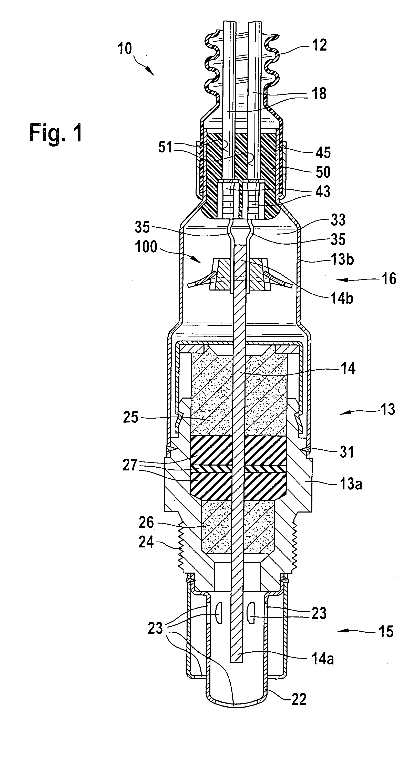
[0017]FIG. 1 shows a gas sensor 10, a lambda sensor or a broadband lambda sensor for example. Gas sensor 10 includes a measuring-side section 15 and a connecting-side section16 and has a metallic housing 13 which is indicated in measuring-side section 15 using reference numeral 13a and in connecting-side section 16 using reference numeral 13b. A planar, oblong sensor element 14 is fixed in a gas-tight manner in housing 13 using ceramic moldings 25, 26 and a sealing element 27. In its connecting-side section 16, gas sensor 10 is connected to a cable jacket 12 in which connector cables 18 for sensor element 14 are routed.

[0018] A protective pipe 22 having gas inlet orifices and gas outlet orifices 23 is mounted on measuring-side section 13a of housing 13. Protective pipe 22 encloses a measuring-side end 14a of sensor element 14 which protrudes from measuring-side section 13a of housing 13. A thread 24, with which gas sensor 10 may be mounted in an exhaust pipe (not shown), is additio...


PUM


Abstract

A gas sensor for determining a physical property of a measuring gas, in particular for determining the temperature of the measuring gas or the concentration of a gas component of the measuring gas. The gas sensor has a sensor element, at least one contact surface situated on the sensor element, and a contact piece electrically connected to the contact surface. The contact piece is clamped in a friction-type manner between the contact surface and at least one press-on body which is clamped against the sensor element by a spring element. The spring element at least partially grips around the press-on body and has a groove.

Description

BACKGROUND INFORMATION [0001] A gas sensor is described in European Patent No. EP 0 506 897 for example. The gas sensor has a sensor element including outside contact surfaces at one end which are electrically connected to contact pieces, via which, for example, the signal of the sensor element is guided out of a housing of the gas sensor. Using a spring element gripping around the sensor element, the contact pieces are clamped in a friction-type manner between the contact surface and a press-on body which is clamped against the sensor element by the spring element. [0002] It is disadvantageous in such gas sensors that the spring element has a comparatively steep characteristic curve of spring so that, even through small manufacturing fluctuations, either the force exerted by the spring element is too small, resulting in a poor contact of the sensor element, or a contact element is damaged when the spring element is attached. [0003] Furthermore, a gas sensor is described in German P...

Claims


Application Information

Patent Timeline
IPC IPC(8): G01N27/407
CPCG01N27/407G01N27/4062
Inventor WEYL, HELMUTWILDE, JUERGENPESCH, ANDREAS
Owner ROBERT BOSCH GMBH
Why Eureka
Try Eureka