Pneumatic Tire

a technology of pneumatic tires and tires, applied in the direction of wheels, vehicle components, non-skid devices, etc., can solve the problems of uneven wear of treads, and inability to effectively drained water screens to the other circumferential grooves, so as to improve drainage characteristics, maintain drainage characteristics, and improve the effect of drainage characteristics

Inactive Publication Date: 2008-02-14
YOKOHAMA RUBBER CO LTD
View PDF4 Cites 5 Cited by
  • Summary
  • Abstract
  • Description
  • Claims
  • Application Information

AI Technical Summary

Benefits of technology

[0006] An object of the present invention is to provide a pneumatic tire having assistant grooves to enh

Problems solved by technology

This pneumatic tire can effectively drain water that has flowed into the lateral grooves by cutting water screen on road surfaces from the one ends of the lateral grooves to the one circumferential groove communicating therewith; however, since the other ends of the lateral grooves does not communicate with the another circumferential groove, the water flowed thereinto by cutting the water screen can not effectively be drained to

Method used


Image

  • Pneumatic Tire
  • Pneumatic Tire

Examples


example 1

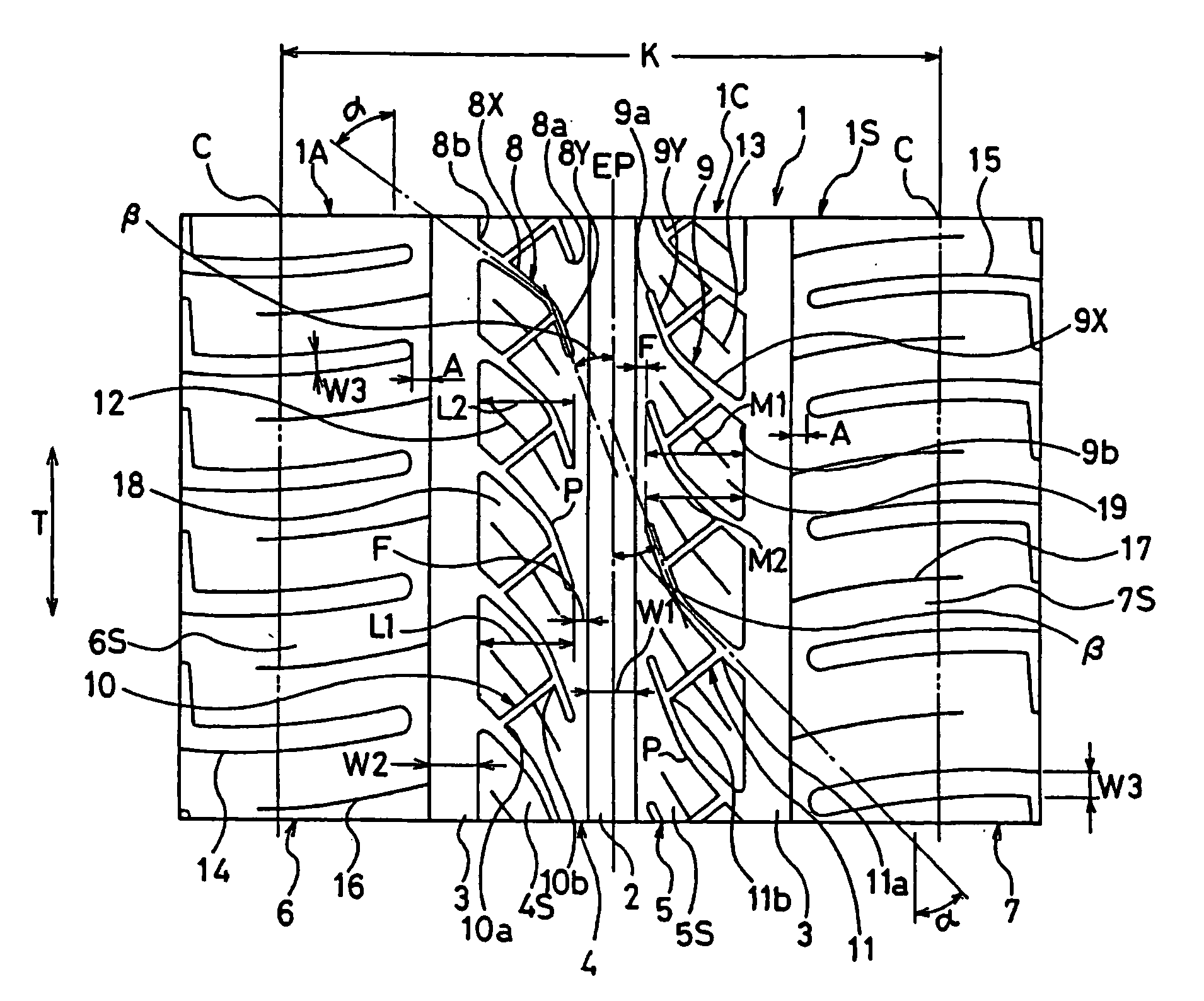
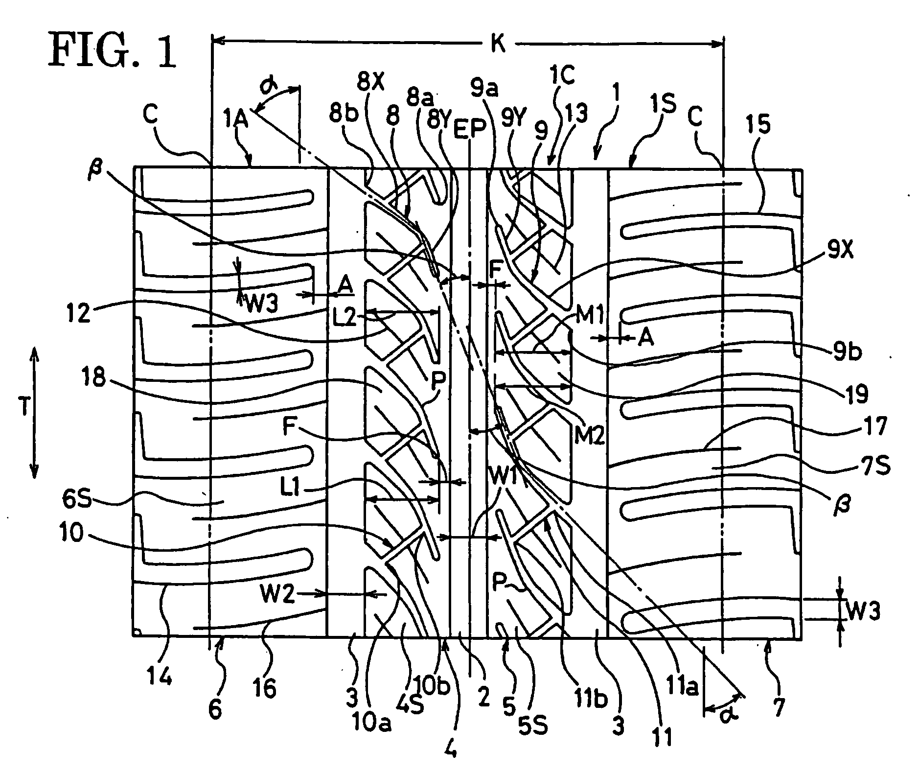
[0046] Prepared were test tires according to the present invention tires 1 to 3, comparison tires 1 and 2, and conventional tire, each having a tire size of 195 / 65R15 and a tread pattern shown in FIG. 1, in which the inclination angles a and β of the first and second inclined groove portions of each middle lateral groove, the communicating position (from the outer terminal end of the one middle lateral groove) of one terminal end and communicating position (from the inner terminal end of the other middle lateral groove) of the other terminal end of each assistant groove communicating with the middle lateral grooves were as shown in Table 1.

[0047] The test tires are the same in construction except for the structures shown in Table 1, and are as shown in the following.

[0048] Width of First Circumferential Groove: 11 mm

[0049] Width of Second Circumferential Groove: 11 mm

[0050] Sum of Widths of First and Second Circumferential Grooves: 24% of the tire contact width K

[0051] Connecti...

example 2

[0061] Prepared were test tires according to the present invention tires 4 to 6 and comparison tires 3 and 4, each having the same tire size and tread pattern as in Example 1, in which the inclination angles a and β of the first and second inclined groove portions of each middle lateral groove, the communicating position (from the outer terminal end of the one middle lateral groove) of one terminal end and communicating position (from the inner terminal end of the other middle lateral groove) of the other terminal end of each assistant groove communicating with the middle lateral grooves were as shown in Table 2. The test tires are the same in construction as in Example 1 except for the structures shown in Table 2.

[0062] Evaluation testing for drainage characteristics and uneven wear resistance was carried out on the test tires according to the test methods shown in Example 1, obtaining the results shown in Table 2.

TABLE 2Com-PresentPresentPresentCom-parisonInventionInventionInve...

example 3

[0064] Prepared were test tires according to the present invention tires 7 to 9 and comparison tires 5 and 6, each having the same tire size and tread pattern as in Example 1, in which the inclination angles a and β of the first and second inclined groove portions of each middle lateral groove, the communicating position (from the outer terminal end of the one middle lateral groove) of one terminal end and communicating position (from the inner terminal end of the other middle lateral groove) of the other terminal end of each assistant groove communicating with the middle lateral grooves were as shown in Table 3. The test tires are the same in construction as in Example 1 except for the structures shown in Table 3.

[0065] Evaluation testing for drainage characteristics and uneven wear resistance was carried out on the test tires according to the test methods shown in Example 1, obtaining the results shown in Table 3.

TABLE 3Com-PresentPresentPresentCom-parisonInventionInventionInve...


PUM


Abstract

A pneumatic tire includes a tread surface having a middle rib defined by a first circumferential groove and a second circumferential groove in its center region. Middle lateral grooves, that obliquely extend in the widthwise direction of the tire, are disposed at predetermined intervals in the tire circumferential direction in the middle rib; only one terminal end of each middle lateral groove communicates with one circumferential groove of the first and second circumferential grooves. An assistant groove is provided between each of adjacent middle lateral grooves; the assistant groove extends in such an inclined manner that the inclination direction thereof with respect to the tire circumferential direction is opposite to that of the middle lateral grooves; a block is defined by the assistant groove, middle lateral grooves and one circumferential groove. The middle lateral grooves each include a first inclined groove portion having an inclination angle a ranging from 35 degrees to 60 degrees and a second inclined groove portion having an inclination angle β ranging from 0 degree to 30 degrees. One terminal end of the assistant groove is located at a position ranging from 20% to 30% of the tire-widthwise length of one middle lateral groove of the adjacent middle lateral grooves from the one terminal end of the one middle lateral groove toward the other terminal end side of the one middle lateral groove in the tire widthwise direction. The other terminal end of the assistant groove is located at a position ranging from 20% to 30% of the tire-widthwise length of the other middle lateral groove of the adjacent middle lateral grooves from the other terminal end of the other middle lateral groove toward the one terminal end side of the other middle lateral groove in the tire widthwise direction.

Description

TECHNICAL FIELD [0001] The present invention relates to pneumatic tires, and more particularly, to a pneumatic tire adapted especially for passenger cars, which can improve uneven wear while maintaining drainage characteristics. TECHNICAL BACKGROUND [0002] Conventionally, there are pneumatic tires, in particular pneumatic passenger tires, including a tread surface having lateral grooves provided in its center region at predetermined intervals in the circumferential direction of the tires in order to enhance an effect of cutting water screen on road surfaces and removing it, the lateral grooves being inclined at a relatively small angle of, for example, about 10 to 45 degrees with respect to the tire circumferential direction. One of such pneumatic tires is arranged such that the inclined lateral grooves communicate at one ends with one circumferential groove and does not communicate at the other ends with another circumferential groove, the other ends being located within a rib. [00...

Claims


Application Information

Patent Timeline
IPC IPC(8): B60C19/00
CPCB60C11/0306B60C11/12B60C11/033Y10T152/10018Y10S152/03Y10S152/901B60C2011/0374
Inventor YAMANE, KENJI
Owner YOKOHAMA RUBBER CO LTD
Why Eureka
Try Eureka