Papermaking fabric

a papermaking fabric and fabric technology, applied in the field of papermaking fabrics, can solve the problems of reducing dewatering performance, paper produced on such known fabrics often showing hydraulic marking, and dimensional stability of fabric, so as to improve drainage characteristics, improve dimensional stability, and improve the porosity of composite structures

Inactive Publication Date: 2013-06-11
VOITH PATENT GMBH
View PDF5 Cites 0 Cited by
  • Summary
  • Abstract
  • Description
  • Claims
  • Application Information

AI Technical Summary

Benefits of technology

[0012]According to a first embodiment of the present invention, the porosity of the composite structure varies along a section of the thickness direction. Therefore, according this embodiment of the present invention, the composite structure may have different porosities at different thickness levels of the composite structure. It is understood that at a thickness level with a high amount of polymeric material, often the porosity of the composite structure is lower compared with a thickness level with a lower amount of polymeric material. Therefore, the composite structure of the industrial fabric may have a varying permeability in the thickness direction, which is the main drainage direction. Accordingly, the fabric has improved drainage characteristics which may be adjusted to the specific operational requirements of the fabric. The thickness of the batt fiber structure is defined by the distance from the upper to the lower surface of the batt fiber layer, measured along a thickness direction.
[0015]To improve the dimensional stability of the fabric of the present invention, the batt fiber structure may be needled to a base cloth. The base cloth can be woven or non-woven or spiral link fabric or a combination thereof. The base cloth extends parallel to the upper and lower surface of the batt fiber structure. Different positions of the base cloth relative to the upper and lower surface of the batt fiber structure are possible. According to fourth embodiment of the present invention, the base cloth is located between the upper and lower surfaces. Thus, the base cloth is positioned inside the batt fiber structure. According to an alternative embodiment the lower surface of the batt layer structure adjoins the base cloth.
[0016]According to a fifth embodiment of the present invention, the distance between the upper and the lower surface defines the total thickness of the batt fiber structure and the amount of polymeric material in the batt fiber structure decreases from the upper surface towards the lower surface. According to this embodiment of the present invention, the porosity of the composite structure can increase from the upper surface, e.g., the paper contacting surface of the fabric, toward the lower surface, e.g., the surface connected to the base cloth or the machine contacting surface, to provide improved drainage characteristics as a result of decreasing dewatering pressure from the paper contacting surface towards the opposing surface.
[0019]According to a seventh embodiment of the present invention, the porosity of the composite structure at a thickness level where the composite structure is formed from a batt layer with coarse fibers is lower than at a thickness level where the composite structure is formed from a batt layer with less coarse fibers.
[0043]To also partly impregnate the reinforcing base cloth with the polymeric material for improved delaminating resistance of the fabric, the method may further include the step of needling the batt fiber structure to a base cloth before the particulate polymeric material is applied to the batt fiber structure. The particulate polymeric material may also at least partly penetrate into the base cloth.

Problems solved by technology

Such impermeable belts have a smooth paper contacting surface but the paper produced on those belts often show a two sidedness.
In addition, use of such impermeable belts results in reduced dewatering performance.
However, paper produced on such known fabrics often show hydraulic marking due to improvable drainage characteristics of such porous fabrics.

Method used


Image

  • Papermaking fabric
  • Papermaking fabric
  • Papermaking fabric

Examples


second embodiment

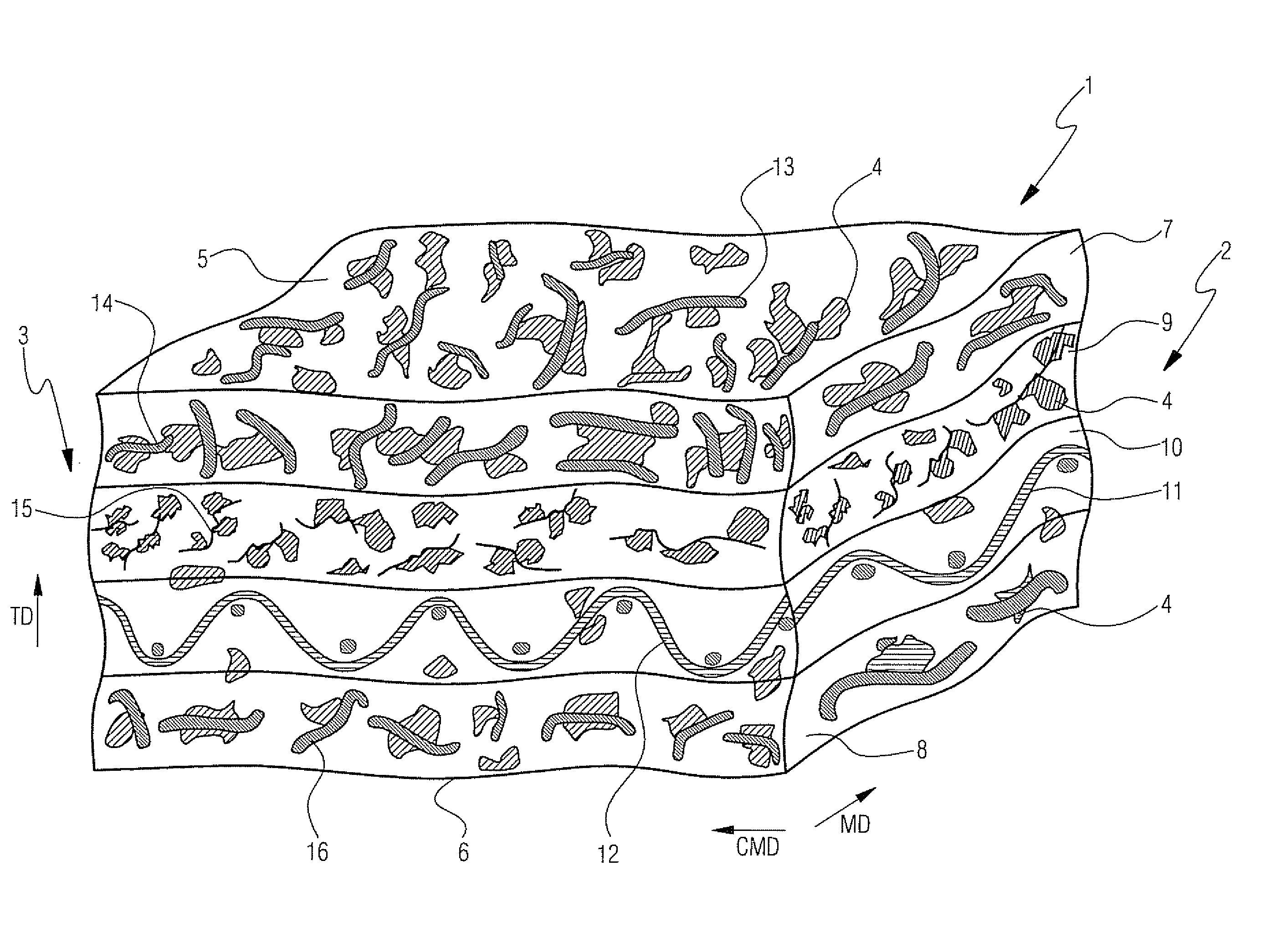
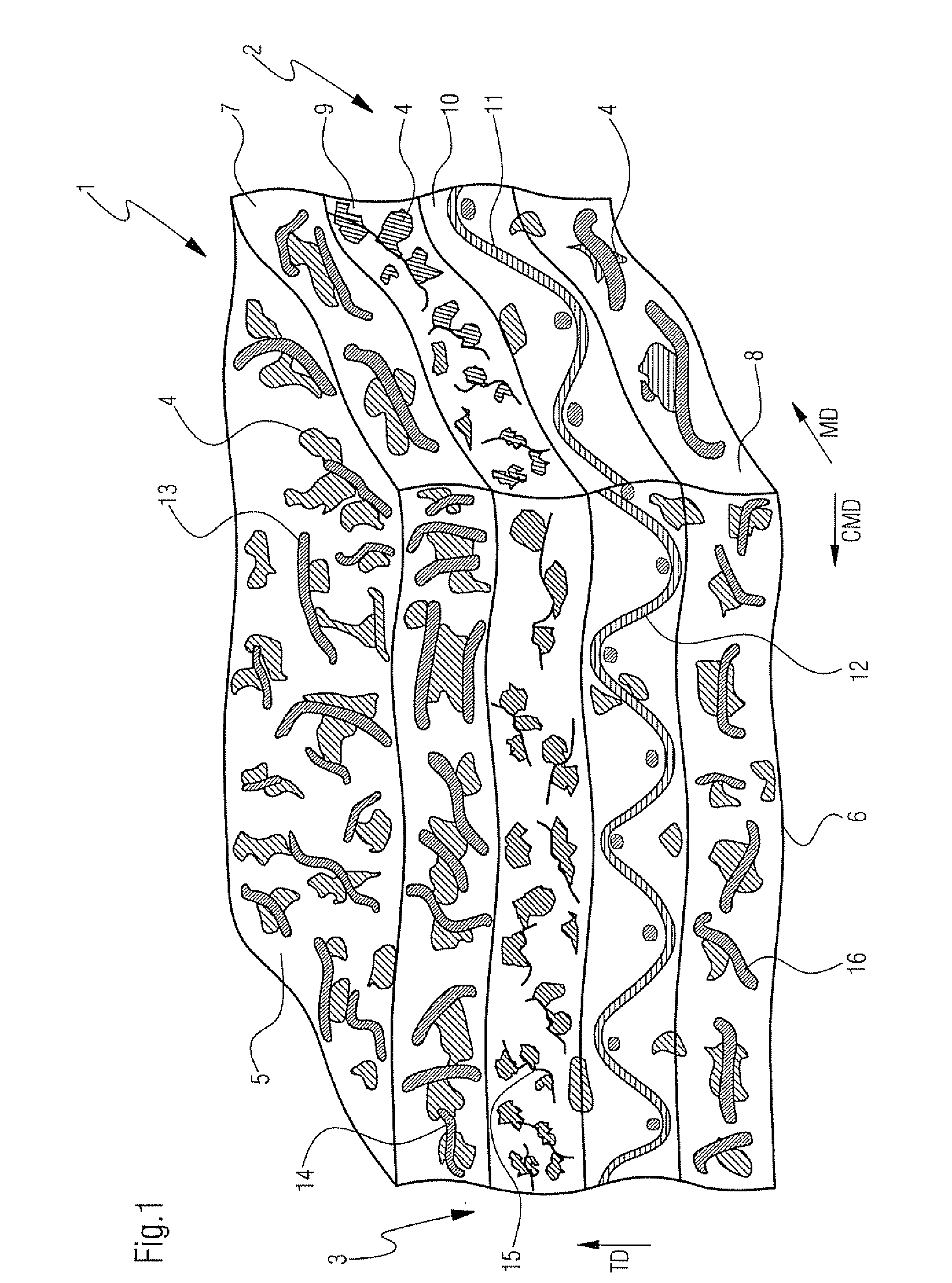
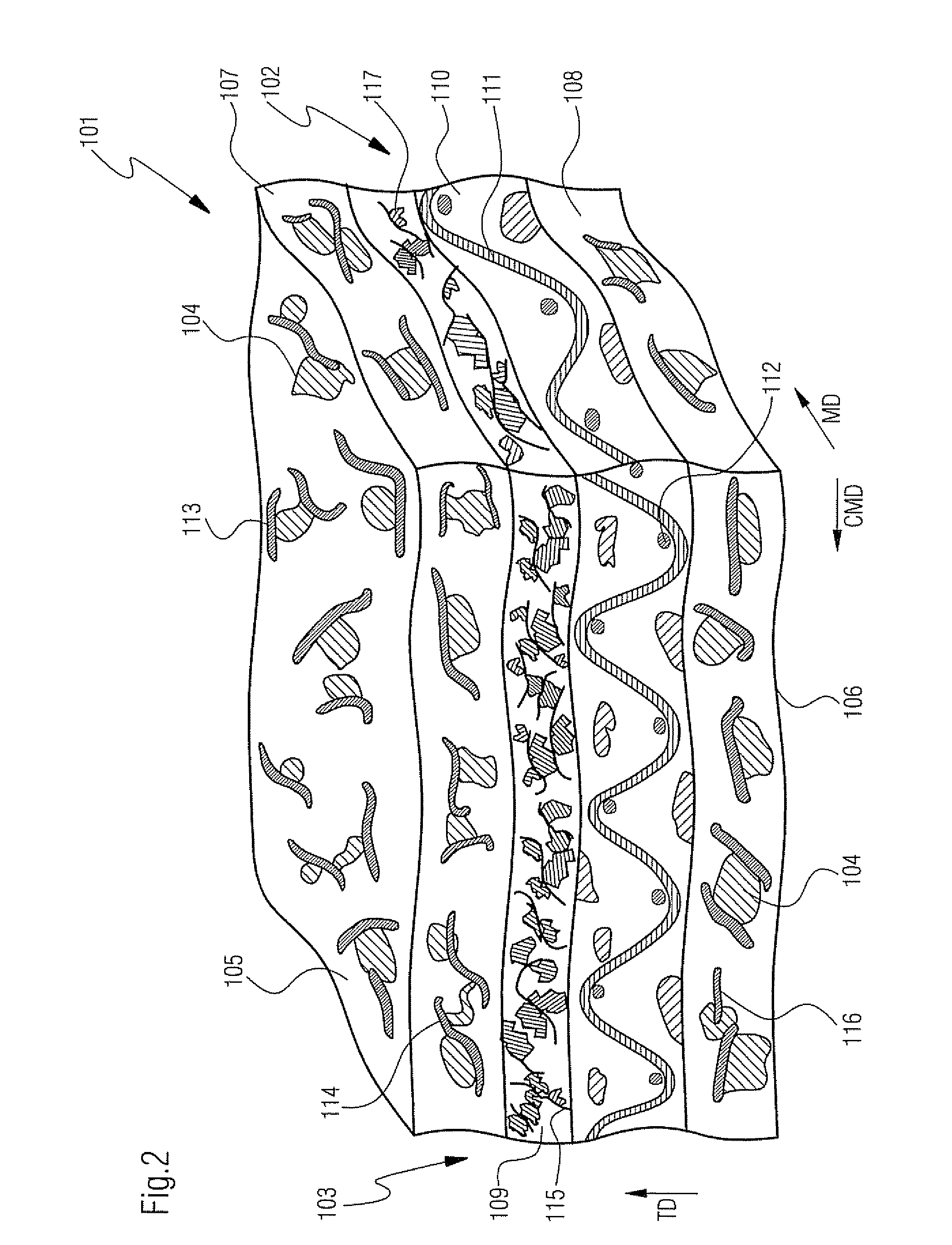
[0058]Referring now to FIG. 2, there is shown press fabric 101 according to the present invention for use in a papermaking machine. Fabric 101 has porous composite structure 102. Composite structure 102 includes batt fiber structure 103 and particulate polymeric material 104 and 117. Batt fiber structure 103 has upper surface 105 and lower surface 106 extending parallel to upper surface 105 and spaced from upper surface 105 along thickness direction TD extending perpendicular to upper surface 105 and lower surface 106.

[0059]Batt fiber structure 103 includes upper coarse batt layer 107, lower coarse batt layer 108 and intermediate less coarse batt layer 109. Upper coarse batt layer 107 has fibers in the range of approximately 22 to 67 dtex, wherein lower coarse batt layer 108 has fibers in the range of approximately 22 to 44 dtex. Intermediate less coarse batt layer 109 is made from fibers in the range from approximately 3.3 to 11 dtex. Upper coarse batt layer 107 is stacked on top o...

third embodiment

[0067]Referring now to FIG. 3 there is shown press fabric 201 according to the present invention for use in a papermaking machine. Fabric 201 has porous composite structure 202. Composite structure 202 includes batt fiber structure 203 and particulate polymeric material 204. Batt fiber structure 203 has upper surface 205 and lower surface 206 extending parallel to upper surface 205 and spaced from upper surface 205 along thickness direction TD extending perpendicular to upper surface 205 and lower surface 206.

[0068]Batt fiber structure 203 includes upper coarse batt layer 207 and lower less coarse batt layer 209. Upper coarse batt layer 207 has fibers in the range of approximately 22 to 44 dtex, wherein lower less coarse batt layer 209 has fibers in the range of approximately 11 to 22 dtex. Upper coarse batt layer 207 is stacked on top of lower less coarse batt layer 209. Less coarse batt layer 209 is stacked on top of woven base cloth 210, woven from MD and CMD orientated yarns 211...


PUM

PropertyMeasurementUnit
sizeaaaaaaaaaa
sizeaaaaaaaaaa
sizeaaaaaaaaaa

Abstract

The present invention relates to an industrial fabric, in particular press fabric or transfer belt, for use in a papermaking machine. The industrial fabric includes a porous composite structure, having a batt fiber structure and particulate polymeric material. The batt fiber structure has an upper surface and a lower surface extending parallel to the upper surface and spaced from the upper surface along a thickness direction extending perpendicular to the upper and lower surface. The particulate polymeric material is partly fused together and bonded with fibers extending on at least one of the surfaces of the batt fiber structure and with fibers inside the batt fiber structure such that the polymeric material partly impregnates fibers of the batt structure and partly fills interstices between fibers of the batt structure to form the porous composite structure. Further in accordance with the present invention, the composite structure has a varying amount of polymeric material in the batt fiber structure along at least a section of the thickness direction of the batt fiber structure. The present invention further provides a method of making same.

Description

CROSS REFERENCE TO RELATED APPLICATIONS[0001]This is a continuation of PCT application No. PCT / EP2008 / 055156, entitled “PAPERMAKING FABRIC”, filed Apr. 28, 2008, which is incorporated herein by reference.BACKGROUND OF THE INVENTION[0002]1. Field of the Invention[0003]The present invention relates to a press fabric or transfer belt for use in the press section of a papermaking machine and to a method of making an industrial fabric according to the present invention.[0004]2. Description of the Related Art[0005]The demands on printability for graphical papers and graphical boards has consistently increased during recent years. The latest generation of press sections has often been designed to eliminate the open draw between the press and the dryer section. This means that the paper web is totally supported by fabrics all through the press section and, therefore, has no contact with smooth plain press rolls. Thus, the demands on press fabrics' surface smoothness and contact area have al...

Claims


Application Information

Patent Timeline
Patent Type & Authority Patents(United States)
IPC IPC(8): D21F7/08B32B27/40B32B27/04
CPCD21F7/083Y10T442/2861Y10T442/3764
Inventor RAGVALD, HANSKARLSSON, KJELL ANDERSBERTILSSON, ANDERSNORD, PIA DELA
Owner VOITH PATENT GMBH
Why Eureka
Try Eureka