High resolution autostereoscopic display apparatus with interlaced image

a display apparatus and high-resolution technology, applied in the field of high-resolution auto-stereoscopic display, can solve the problems of high loss of light due to parallax barrier, complex additional structure, and high cost of light deflecting unit formed of ferroelectric liquid crystal

Inactive Publication Date: 2008-02-14
SAMSUNG ELECTRONICS CO LTD
View PDF6 Cites 93 Cited by
  • Summary
  • Abstract
  • Description
  • Claims
  • Application Information

AI Technical Summary

Benefits of technology

[0014]Exemplary embodiments of the present invention also provide a high resolution autostereoscopic display apparatus with an interlaced image that can use a conventional LCD panel, that is, not using an expensive high speed responsive LCD.
[0031]The lenticular lens sheet may allow the light passing through the first birefringent elements to proceed towards the first viewing zone and the light passing through the second birefringent elements to proceed towards the second viewing zone.

Problems solved by technology

Also, in order to enable a switching action between a 2-D image mode and a 3-D image mode, a very complicated additional structure is needed.
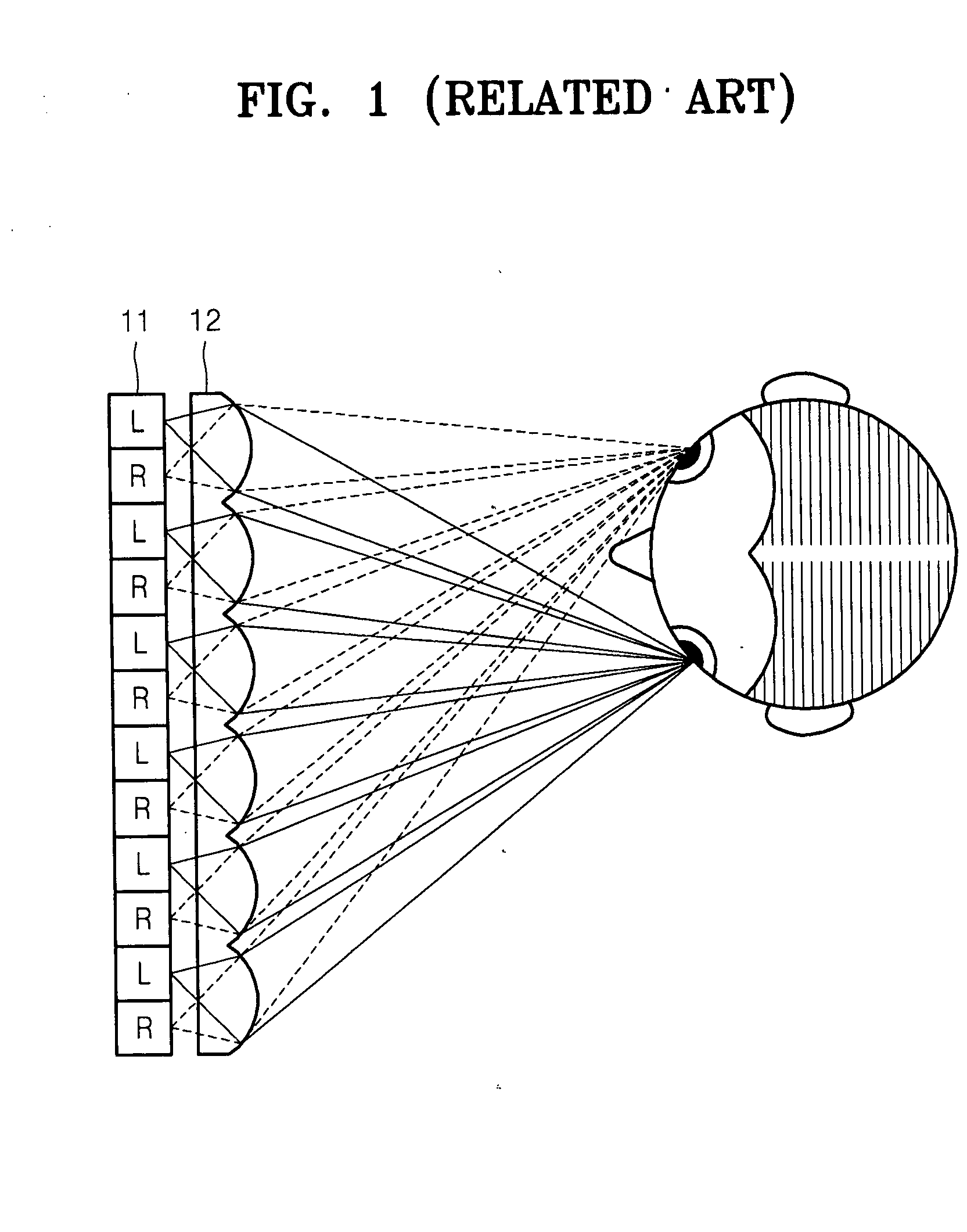
However, there is a problem in that the light deflecting unit formed of ferroelectric liquid crystal is very expensive and the loss of light due to the parallax barrier is high.
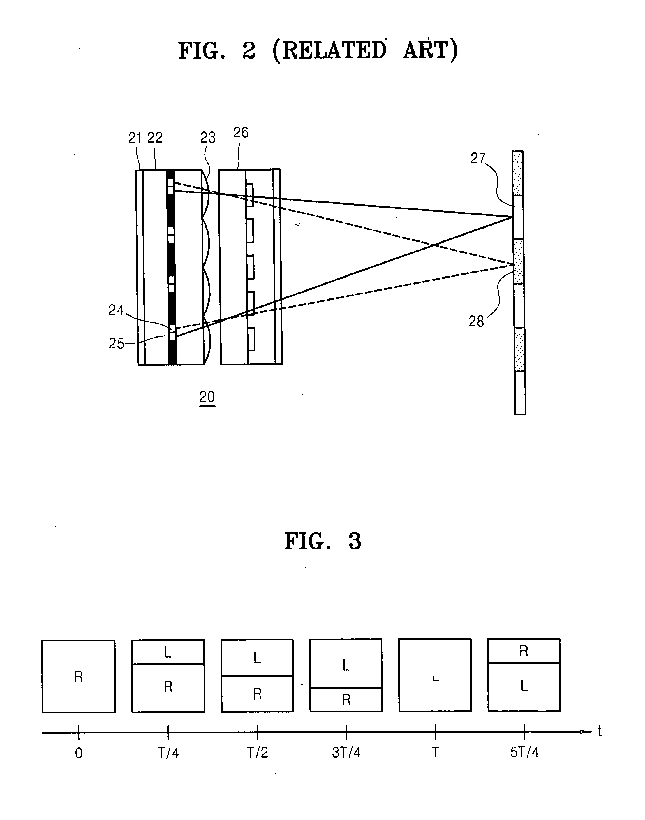
However, in the time-sharing type methods of the above-discussed Japanese publication and U.S. patent, cross talk is generated between the left eye image and the right eye image so that the user is not able to view an accurate 3-D image.
Also, the above-described Japanese publication and U.S. patent have a problem of using an expensive high speed responsive LCD display panel in order to prevent a flickering phenomenon.
Thus, the conventional LCD display panel having a vertical scanning speed of 60-75 Hz cannot be used for the related art time-sharing type autostereoscopic display apparatus.

Method used


Image

  • High resolution autostereoscopic display apparatus with interlaced image
  • High resolution autostereoscopic display apparatus with interlaced image
  • High resolution autostereoscopic display apparatus with interlaced image

Examples


Embodiment Construction

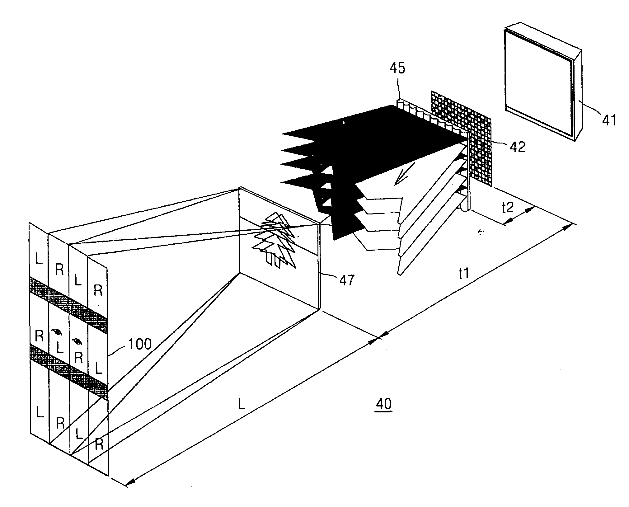
[0074]FIG. 5 is an exploded perspective view schematically illustrating the structure of a high resolution autostereoscopic display apparatus 30 according to an exemplary embodiment of the present invention. Referring to FIG. 5, the high resolution autostereoscopic display apparatus 30 in the present embodiment includes a division type backlight unit 31; a polarizing plate 32 which only transmits light, incident from the backlight unit 31, having a particular polarization direction; a spatial light modulator 33 changing the polarization direction of incident light according to electric control; a first birefringent element array 34 in which a plurality of first and second vertical birefringent elements 34a and 34b, alternately arranged along the horizontal direction, which change the polarization direction of incident light; a lenticular lens sheet 35 separating the incident light into a left eye viewing zone and a right eye viewing zone; a second birefringent element array 36 in wh...


PUM


Abstract

An autostereoscopic display apparatus includes a backlight unit, a polarizing plate disposed in front of the backlight unit; a display panel displaying a left eye image and a right eye image by interlacing pixel lines of the left and right eye images alternately and sequentially; a lenticular lens sheet, disposed between the polarizing plate and the display panel, separating light emitted from the backlight unit into a left eye zone and a right eye zone; and a polarization switch controlling a polarization direction of light proceeding towards the left eye viewing zone so that light is incident on pixel lines of the display panel displaying the left eye image and a polarization direction of light proceeding towards the right eye viewing zone so that light is incident on pixel lines of the display panel displaying the right eye image, in synchronization with a vertical scanning time of the display panel.

Description

CROSS-REFERENCE TO RELATED PATENT APPLICATIONS[0001]This application claims the benefit of Korean Patent Application No. 10-2006-0067301, filed on Jul. 19, 2006, in the Korean Intellectual Property Office, and the benefit of U.S. Provisional Patent Application No. 60 / 797,373, filed on May 4, 2006, in the U.S. Patent and Trademark Office, the disclosures of which are incorporated herein in their entirety by reference.BACKGROUND OF THE INVENTION[0002]1. Field of the Invention[0003]Apparatuses consistent with the present invention relate to a high resolution autostereoscopic display, and more particularly, to a high resolution autostereoscopic display apparatus in which resolution is not decreased and cross talk does not occur as an image is displayed in an interlaced method.[0004]2. Description of the Related Art[0005]An autostereoscopic display apparatus is used to display an image for the left eye and an image for the right eye that exhibit binocular parallax respectively to the lef...

Claims


Application Information

Patent Timeline
Patent Type & Authority Applications(United States)
IPC IPC(8): H04N15/00
CPCH04N13/0418H04N13/0404H04N13/305H04N13/32H04N13/00
Inventor SHESTAK, SERGEYKIM, DAE-SIKJUNG, SUNG-YONG
Owner SAMSUNG ELECTRONICS CO LTD
Why Eureka
Try Eureka