Al technical title is built by PatSnap Al team. It summarizes the technical point description of the patent document.
An optical lens and lens technology, applied in the field of optical lens, can solve the problems of high pixel and small distortion, and achieve the effect of small distortion
Inactive Publication Date: 2015-01-21
NINGBO SUNNY AUTOMOTIVE OPTECH
View PDF0 Cites 58 Cited by
Summary
Abstract
Description
Claims
Application Information
AI Technical Summary
This helps you quickly interpret patents by identifying the three key elements:
Problems solved by technology
Method used
Benefits of technology
Problems solved by technology
[0003] At present, the wide-angle indoor monitoring and vehicle-mounted camera lenses on the market cannot meet th
Method used
Image
Click on the blue label to locate the original text in one second.
Reading with bidirectional positioning of images and text.
Examples
Embodiment 1
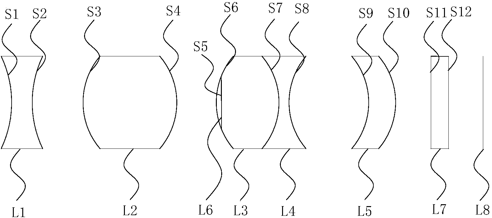
[0051] figure 1 It is a structural schematic diagram of an optical lens provided in a specific embodiment of the present invention. like figure 1 As shown, an optical lens according to the present invention, from the object side to the image side, includes: a front lens group with positive refractive power, an aperture element L6, a rear lens group with positive refractive power, and a color filter L7, imaging surface L8,
[0052] Wherein, the front lens group includes in sequence from the object side to the image side: a first lens L1 and a second lens L2, the first lens L1 is a biconcave lens with negative refractive power, and the second lens L2 is A biconvex lens with positive refractive power; the rear lens group includes in sequence from the object side to the image side: a third lens L3, a fourth lens L4, and a fifth lens L5, the third lens L3 and the fourth lens L4 A cemented lens is formed, the fifth lens L5 is an aspheric mirror with positive refractive power, and...
Embodiment 2
[0094] Embodiment 2: It should be noted that the difference between this embodiment and Embodiment 1 lies in that the structure of the cemented lens in the rear lens group in this embodiment is different, and the orientation of the two concave surfaces of the fifth lens L5 is different.
[0095] Figure 5 It is a structural schematic diagram of another optical lens provided in the specific embodiment of the present invention. like Figure 5 As shown, an optical lens according to the present invention, from the object side to the image side, includes: a front lens group with positive refractive power, an aperture element L6, a rear lens group with positive refractive power, and a color filter L7, imaging surface L8;
[0096] Wherein, the front lens group includes in sequence from the object side to the image side: a first lens L1 and a second lens L2, the first lens L1 is a biconcave lens with negative refractive power, and the second lens L2 is A biconvex lens with positive...
PUM
Abstract
The invention relates to an optical lens which sequentially comprises a front lens group with positive focal power, a diaphragm element and a rear lens group with positive focal power from the object space to the image space. The front lens group sequentially comprises a first lens and a second lens from the object space to the image space. The first lens is a biconcave lens with negative focal power. The second lens is a biconvex lens with positive focal power. The rear lens group sequentially comprises a third lens, a fourth lens and a fifth lens from the object space to the image space. A gluing lens is formed by the third lens and the fourth lens. The fifth lens is an aspheric surface lens with positive focal power, and two concave faces of the fifth lens are in the same-direction crescent shape. According to the optical lens, high pixels, small deformation and large apertures can be achieved under the condition that the requirements for low cost and miniaturization are met, a perfect image can still be kept within the temperature range of -40 DEG C to 85 DEG C, and the optical lens is particularly suitable for monitors and vehicle-mounted camera systems which work in the day and at night or under a poor illumination condition.
Description
technical field [0001] The invention relates to the technical field of optical imaging, in particular to an optical lens. Background technique [0002] With the development of active safety in the automotive industry, the requirements for vehicle front-view lenses continue to increase. Small distortion, miniaturization, megapixels, and large-aperture lenses are already necessary conditions for this type of lens. In addition, low cost is required, and perfect imaging clarity is maintained in the temperature range of -40°C to +85°C. [0003] The wide-angle indoor surveillance and vehicle-mounted camera lenses currently on the market are not yet able to achieve high-pixel, small-distortion, and large-aperture imaging under the conditions of low cost and miniaturization. Contents of the invention [0004] The purpose of the present invention is to propose an optical lens that can achieve high pixel, small distortion, and large aperture while meeting the requirements of low c...
Claims
Application Information
Patent Timeline
Application Date:The date an application was filed.
Publication Date:The date a patent or application was officially published.
First Publication Date:The earliest publication date of a patent with the same application number.
Issue Date:Publication date of the patent grant document.
PCT Entry Date:The Entry date of PCT National Phase.
Estimated Expiry Date:The statutory expiry date of a patent right according to the Patent Law, and it is the longest term of protection that the patent right can achieve without the termination of the patent right due to other reasons(Term extension factor has been taken into account ).
Invalid Date:Actual expiry date is based on effective date or publication date of legal transaction data of invalid patent.