Input and output device and terminal device

a terminal device and input and output technology, applied in the direction of instruments, computing, electric digital data processing, etc., can solve the problems of inability to obtain sensing like drawing characters and figures with a pen, low display quality, and low image depth, so as to reduce the depth of image feel, low cost, and high display quality

Inactive Publication Date: 2005-12-22
NEC LCD TECH CORP
View PDF7 Cites 56 Cited by
  • Summary
  • Abstract
  • Description
  • Claims
  • Application Information

AI Technical Summary

Benefits of technology

[0024] According to the invention, since the loci of light outgoing from the first and second pixels driven based on the identical signal intersect with each other, a user can be made to recognize a virtual display surface on a plane positioned ahead of the actual display surface of the display unit, whereby the depth feel of the image can be reduced. In addition, the input and output device of the invention does not need special parts, so that costs are low, and the display quality is high since light is not diffused.

Problems solved by technology

However, among these, a mouse is used by users for input operation from positions apart from the display screen, so that the sensation like drawing characters and figures with a pen cannot be obtained.
However, the above-described conventional technique has the following problem.
Therefore, when a user looks at these points, the image looks deep and the user has a sense of discomfort.
Due to this “depth feel,” the input operation of the user loses accuracy, and the operation efficiency significantly lowers and makes the user tired.
However, the conventional technique has the following problem.
In addition, since the parallax correcting plate 56 is manufactured by bundling and binding the optical fibers with a resin, it is difficult to manufacture a large-size parallax correcting plate.
Furthermore, the number of optical fibers to be bundled increases in proportion to the area, and therefore, to manufacture a plate with a comparatively large area such as a monitor for a cell phone, a PDA, or a monitor of a personal computer, a large number of fibers must be bundled, and the costs are extremely high.
Therefore, the contrast of the display unit is significantly lowered, and this lowers the operation efficiency of a user.
In addition, since light of the image to be displayed is scattered, for example, when a character is displayed, the character becomes blurred or thicker more than the actual image.
This use of the light diffusion layer lowers the display quality.

Method used


Image

  • Input and output device and terminal device
  • Input and output device and terminal device
  • Input and output device and terminal device

Examples


first embodiment

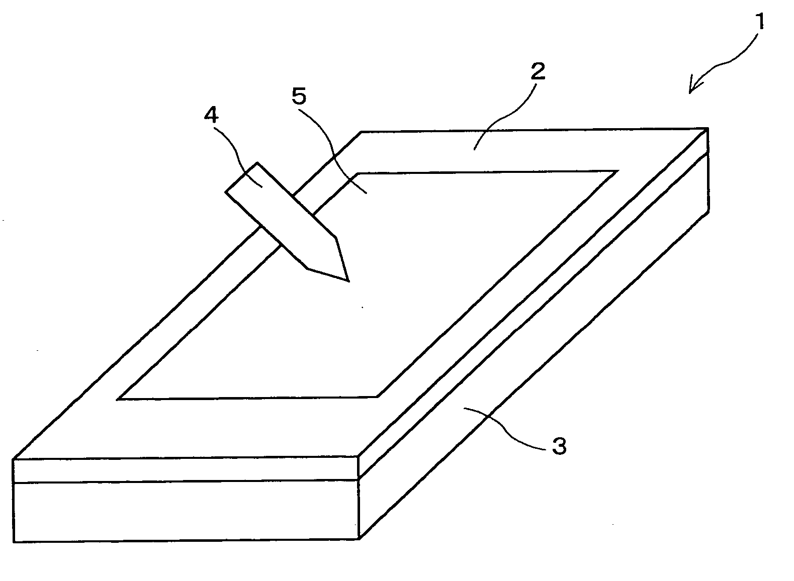
[0038] Hereinafter, embodiments of the present invention are described in detail with reference to the accompanying drawings. First, the invention is described. FIG. 5 is a perspective view showing an input and output device of this embodiment, FIG. 6 is a partial sectional view of the identical, and FIG. 7 is a diagram showing the optical construction thereof. The input and output device of this embodiment is an input and output device mounted in a PDA.

[0039] As shown in FIG. 5, in the input and output device 1 of this embodiment, a liquid crystal display unit 3 as an output unit is provided, and a tablet 2 as an input unit is provided in front of this liquid crystal display unit 3. In front of the tablet 2, an input / output region 5 is provided. In response to pressing of the input / output region 5 with a pen 4 as an input means by a user, data is inputted into the tablet 2. The entirety of the tablet 2 transmits light, and the user can view an image displayed by the liquid crystal ...

second embodiment

[0061] From the formula 5, in this embodiment, a pair of pixels disposed at a distance three times the aligning pitch P of the pixels from each other are made to display an image for the right eye and an image for the left eye corresponding to each other, whereby a user can be made to recognize a virtual display surface almost on the surface of the input and output device, that is, the front face of the tablet 2, and the depth feel can be almost completely eliminated. This means that, as shown in FIG. 9, the pixels 16 and 18 disposed by sandwiching two pixels therebetween are made to display an image for the right eye and an image for the left eye corresponding to each other. Other workings and effects of this embodiment are the identical as those of the

[0062] Next, a fourth embodiment of the invention is described. FIG. 13 shows an optical construction of an input and output device of this embodiment. This embodiment is different from the third embodiment in that a pair of pixels a...

third embodiment

[0063] As shown in FIG. 13, the distance between the eyes of a user is set to 65 mm, the distance L3 between the right eye 13 and left eye 14 and the surface of the input and output device 1 is set to 400 mm. In addition, as described above, the distance T3 from the interface between the liquid crystal layer 12 and the color filter substrate 6 to the front face of the tablet 2 is set to 0.7 mm. Furthermore, the intersection of light rays transmitted through a pair of pixels adjacent to each other, for example, the pixels 16 and 19 shown in FIG. 13 is defined as a point H, the distance from the interface between the liquid crystal layer 12 and the color filter substrate 6 to the intersection H is defined as T4, and the distance from the intersection H to the right eye 13 and left eye 14 of the user is defined as L4. Furthermore, as in the case of the third embodiment, the aligning pitch of the picture elements 41 (see FIG. 12) is 177 micrometers, and the aligning pitch P of pixels is...


PUM


Abstract

A lenticular lens is provided in front of a liquid crystal panel composed of a plurality of pixels. In this case, the lenticular lens is arranged so that one cylindrical lens corresponds to two pixels adjacent to each other. Then, light rays outgoing from two pixels are refracted by this one cylindrical lens and intersect with each other at a point positioned on the surface of a tablet, and then reach the right eye and the left eye of a user, respectively.

Description

BACKGROUND OF THE INVENTION [0001] 1. Field of the Invention [0002] The present invention relates to an input and output device which includes a flat input unit mounted on a display unit, and inputs while displaying characters and figures inputted by handwriting into the flat input unit in real time, and a terminal device using this. Particularly, the present invention can be preferably applicable to input and output devices which are equipped with terminal devices such as cell phones, mobile terminals, PDAs (personal digital assistances), game machines, digital cameras, digital video cameras, and personal computers, and can input data with sensation of handwriting, and terminal devices including the input and output devices. [0003] 2. Description of the Related Art [0004] As means for inputting data into a computer, keyboards are generally known. However, at present, data to be inputted into computers is not only text data composed of arrangement of the alphabet and numerals assign...

Claims


Application Information

Patent Timeline
Patent Type & Authority Applications(United States)
IPC IPC(8): G02B3/00G02B30/27G02B30/30G06F3/033G09G5/00
CPCG02B3/005G06F3/0412G02B27/2214G02B30/27G02B30/30
Inventor IKEDA, NAOYASUUEHARA, SHIN-ICHITAKANASHI, NOBUAKI
Owner NEC LCD TECH CORP
Why Eureka
Try Eureka