Backlight unit and 2d/3d switchable image display device employing the backlight unit

Active Publication Date: 2008-12-25
SAMSUNG ELECTRONICS CO LTD
View PDF4 Cites 55 Cited by
  • Summary
  • Abstract
  • Description
  • Claims
  • Application Information

AI Technical Summary

Benefits of technology

[0013]Exemplary embodiments of the present invention provide a backlight unit which has an improved structure so that its number of optical parts is decreased, the manufacturing process is simpl

Problems solved by technology

However, according to the non-glasses type 3D image display device 1, since the optical switch 5 that is interposed between the backlight unit 3 and the lenticular lens sheet 7 is needed, an assembly process is complicated, and a manufacturing cost of the non-glasses type 3D image display device 1 is increased.
Also, a polarized switch is used as the optical switch 5, which further degrades the light use efficiency.
However, since the non-glasses type 3D image display device 1 needs one frame of the ima

Method used


Image

  • Backlight unit and 2d/3d switchable image display device employing the backlight unit
  • Backlight unit and 2d/3d switchable image display device employing the backlight unit
  • Backlight unit and 2d/3d switchable image display device employing the backlight unit

Examples


Embodiment Construction

[0037]The attached drawings for illustrating exemplary embodiments of the present invention are referred to in order to gain a sufficient understanding of the present invention, the merits thereof, and the objectives accomplished by the implementation of the present invention. Hereinafter, the present invention will be described in detail by explaining exemplary embodiments of the invention with reference to the attached drawings. Like reference numerals in the drawings denote like elements. The size of each of the constituent elements on the drawings may be exaggerated for the clarity and convenience of the explanation.

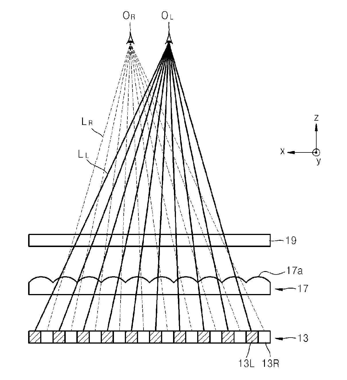
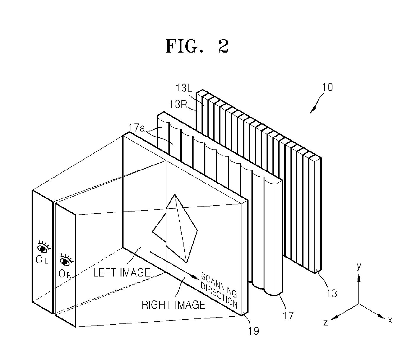
[0038]FIG. 2 illustrates an optical configuration of a 2D / 3D switchable image display device 10 according to an exemplary embodiment of the present invention. FIG. 3 is a cross-sectional view of the 2D / 3D switchable image display device 10 of FIG. 2 viewed from above. FIG. 4 illustrates the structure for inputting image data to an image panel 19 employed in the 2D / 3D...


PUM


Abstract

A 2D/3D switchable image display device is provided. The device includes an image panel, a backlight unit arranged at the rear side of the image panel, and a lenticular lens sheet arranged between the image panel and the backlight unit. The backlight unit includes a plurality of segment light sources for a left eye vision range which emit a light for a left eye vision range, and a plurality of segment light sources for a right eye vision range which emit a light for a right eye vision range. The segment light sources for the left eye vision range and the segment light sources for the right eye vision range are alternately arranged to form a surface light source. The lenticular lens sheet includes a plurality of semi-cylindrical lenses arranged in a direction perpendicular to a viewing direction of both eyes of a viewer.

Description

CROSS-REFERENCE TO RELATED PATENT APPLICATIONS[0001]This application claims priority from Korean Patent Application No. 10-2007-0062487, filed on Jun. 25, 2007 in the Korean Intellectual Property Office, the disclosure of which is incorporated herein in its entirety by reference.BACKGROUND OF THE INVENTION[0002]1. Field of the Invention[0003]Apparatuses consistent with the present invention relate to a backlight unit and a 2D / 3D switchable liquid crystal display (LCD) employing the backlight unit, and more particularly, to a backlight unit having a simple structure of providing light for a left eye vision range and light for a right eye vision range to a lenticular lens sheet, and a 2D / 3D switchable LCD employing the backlight unit.[0004]2. Description of the Related Art[0005]As technology develops, an image display device capable of displaying a more real image is needed. Accordingly, a high resolution image display device having an increased number of pixels for displaying an imag...

Claims


Application Information

Patent Timeline
IPC IPC(8): G02B27/22F21V8/00G02B30/27
CPCG02B27/2214G02B30/27G02F1/1335
Inventor CHA, KYUNG-HOONCHESTAK, SERGEYKIM, DAE-SIK
Owner SAMSUNG ELECTRONICS CO LTD
Why Eureka
Try Eureka