Optical member, backlight unit and display apparatus

a backlight unit and optical member technology, applied in non-linear optics, lighting and heating apparatus, instruments, etc., can solve the problems of not being able to improve the visibility from a plurality of arbitrary directions, above-described conventional techniques

Active Publication Date: 2008-11-27
CITIZEN ELECTRONICS CO LTD
View PDF5 Cites 58 Cited by
  • Summary
  • Abstract
  • Description
  • Claims
  • Application Information

AI Technical Summary

Benefits of technology

[0015]The light-reflecting layer may comprise a light-reflecting layer portion and a light-absorbing layer portion disposed between the light-reflecting layer portion and the transparent member. The light-absorbing layer portion

Problems solved by technology

The above-described conventional techniques, however, still have the following problems to be solved.
In this regard, the first three of the above-described known techniques can improve the visibility of the display screen as viewed from one direction, e.g. from the directly forward direction, but c

Method used


Image

  • Optical member, backlight unit and display apparatus
  • Optical member, backlight unit and display apparatus
  • Optical member, backlight unit and display apparatus

Examples


Embodiment Construction

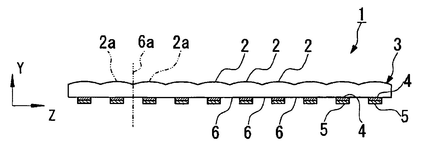
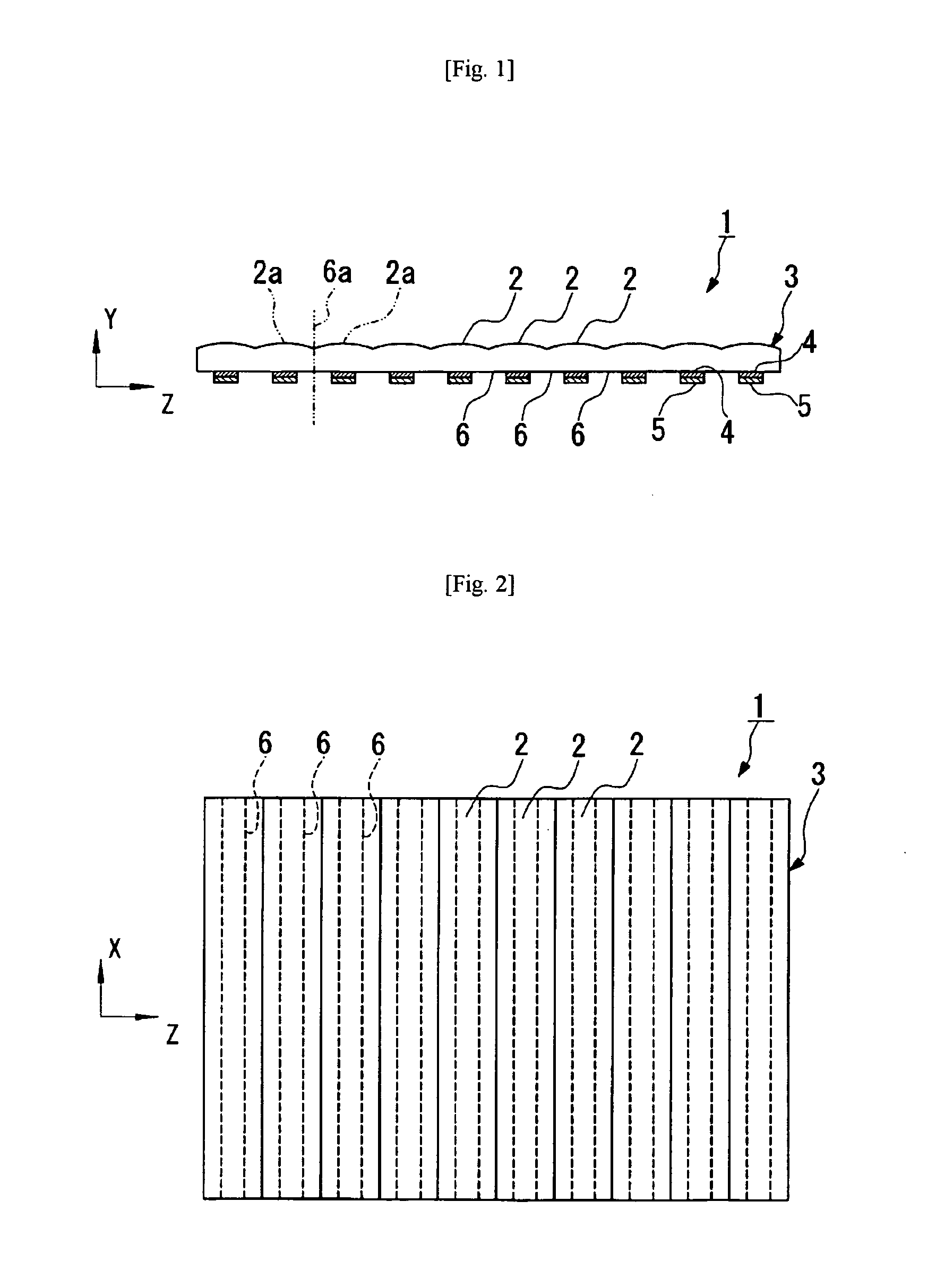
[0037]FIGS. 1 and 2 show an optical member 1 according to an embodiment of the present invention. The optical member 1 has a lenticular lens member (transparent member) 3, a light-absorbing layer portion 4 disposed on the back surface of the lenticular lens member 3, and a light-reflecting layer portion 5 disposed on the back surface of the light-absorbing layer portion 4.

[0038]The lenticular lens member 3 is formed in the shape of a sheet, film or plate from a light-transmitting resin, e.g. an epoxy resin, polyester, polycarbonate, or polyvinyl chloride. The lenticular lens member 3 has on its front surface a plurality of mutually parallel elongated convex lenses 2 having a half-cylindrical shape, i.e. a substantially semicircular cross-section, arranged successively from one edge to the other of the lenticular lens member 3. That is, the lenticular lens member 3 is what is called a micro-lenticular lens array. It should be noted that the material (refractive index, etc.) and thick...


PUM


Abstract

An optical member enables a display apparatus to be improved in visibility of its display screen as viewed from a plurality of predetermined directions other than the directly forward direction. The optical member includes a lenticular lens member (3) having a plurality of convex lenses (2) and a light-reflecting layer (5) disposed on the back surface of the lenticular lens member. The light-reflecting layer (5) is provided with optical windows (6) each at a position corresponding to a midpoint between the apexes of mutually adjacent convex lenses. Light emitted from a planar light source, passed through each optical window (6), and configured to enter the mutually adjacent convex lenses (2) corresponding to the optical window is directed in mutually different directions by the mutually adjacent convex lenses, respectively.

Description

REFERENCE TO THE RELATED APPLICATIONS[0001]This application claims priority under 35 U.S.C. § 119 to Japanese Patent application No. JP2007-123767 filed on May 8, 2007 and Japanese Patent application No. JP2007-123768 filed on May 8, 2007, the entire contents of which are hereby incorporated by reference.TECHNICAL FIELD[0002]The present invention relates to an optical member having directivity in two directions other than a directly forward direction, for example, and also relates to a backlight unit and a display apparatus that use the optical member.RELATED PRIOR ART[0003]Liquid crystal display apparatus for image display have been widely used in mobile phones, personal digital assistants (PDAs), automated teller machines (ATMs), displays of personal computers and car navigation systems, etc. These liquid crystal display apparatus employ a backlight unit that applies illuminating light to a liquid crystal display panel from the back thereof to enhance the luminance of the display ...

Claims


Application Information

Patent Timeline
IPC IPC(8): G02F1/1335G03B21/60F21V7/04
CPCG02B3/0056G02F1/133615G02F2001/133607G02F1/133607
Inventor MIYASHITA, JUNJI
Owner CITIZEN ELECTRONICS CO LTD
Why Eureka
Try Eureka