Dual-mode contour-following mop

a contour-following mop and dual-mode technology, applied in the field of mop, can solve the problems of insufficient weight to create a strong enough cleaning force, inability to adapt to contours, and inability to easily detach in fashion, etc., and achieve the effect of convenient use and cleaning, convenient detachable fashion, and low manufacturing cos

Inactive Publication Date: 2008-02-21
AIYAR SANJAY
View PDF5 Cites 41 Cited by
  • Summary
  • Abstract
  • Description
  • Claims
  • Application Information

AI Technical Summary

Benefits of technology

[0013]The secondary resilient base is affixed to the motor shaft, preferably in a readily detachable fashion. A secondary flexible pad is fixed to the secondary resilient base and includes a cleaning surface on a lower side thereof. The secondary resilient base may instead be a brush or a scraper, for instance. In use, such an embodiment allows for motorized rotational scrubbing of the surface when the fingers are in the compressed orientation and the switch is actuated.
[0014]The present device is a contour-following mop that, in addition to providing padded resilient fingers that may be forced against the surface, further provides a secondary mode wherein direct pressure of a secondary cleaning surface may be applied to clean stubborn debris. The secondary cleaning surface may be a firm scrubbing pad, resilient rubber nibs, brush bristles, or even scraping edges. The present invention further provides means for rotating the secondary cleaning surface to provide a motorized spot cleaning capability. The present device is relatively inexpensive to manufacture, easy to use and clean, and is durable under repeated use. Other features and advantages of the present invention will become apparent from the following more detailed description, taken in conjunction with the accompanying drawings, which illustrate, by way of example, the principles of the invention.

Problems solved by technology

Such mops are made to conform to contours typical of motor vehicles, as a flat mop is essentially useless on such surfaces.
However, such weight is not always sufficient to create a strong enough cleaning force around such contours.
Further, the central area of this device is too rigid and flat to adapt itself to contours.
While such devices do create a stronger cleaning force for cleaning a contoured surface, such devices are not well suited for concentrated scrubbing of areas of the surface that have caked-on or greasy areas in need of cleaning.
For example, bird droppings, oil, or other stubborn grime is difficult to remove with such prior art devices.
The Maupin device is difficult to use due to its loose cleaning pad at the center which tends to interfere with cleaning the surface and, during application of any downward pressure, tends to play one side against the other, thus limiting its effectiveness on contoured surfaces.
This is a drawback from which many prior art devices suffer.
While such a water jet may help remove stubborn debris to some extent, such a device does not provide for a concentrated water jet sufficient for removing all such debris.
Further, a flexible mop pad necessarily is interposed between the water jet and the debris, further reducing the effectiveness of such a device.

Method used


Image

  • Dual-mode contour-following mop
  • Dual-mode contour-following mop
  • Dual-mode contour-following mop

Examples


Embodiment Construction

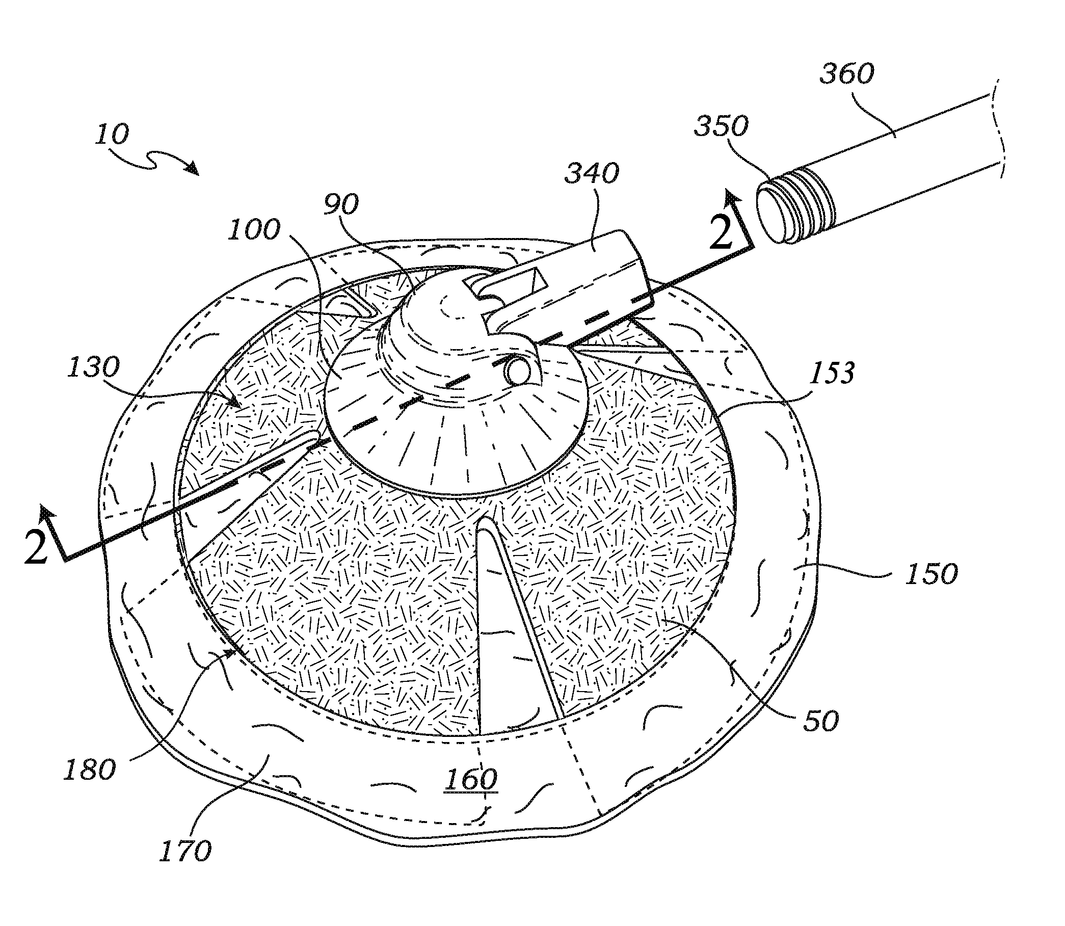
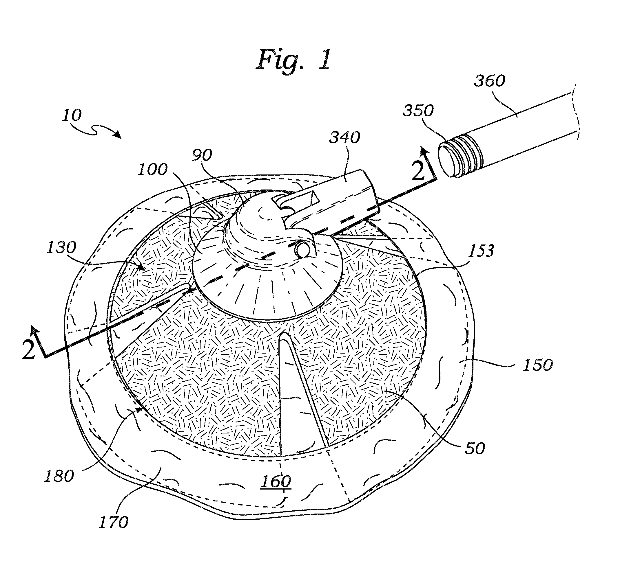
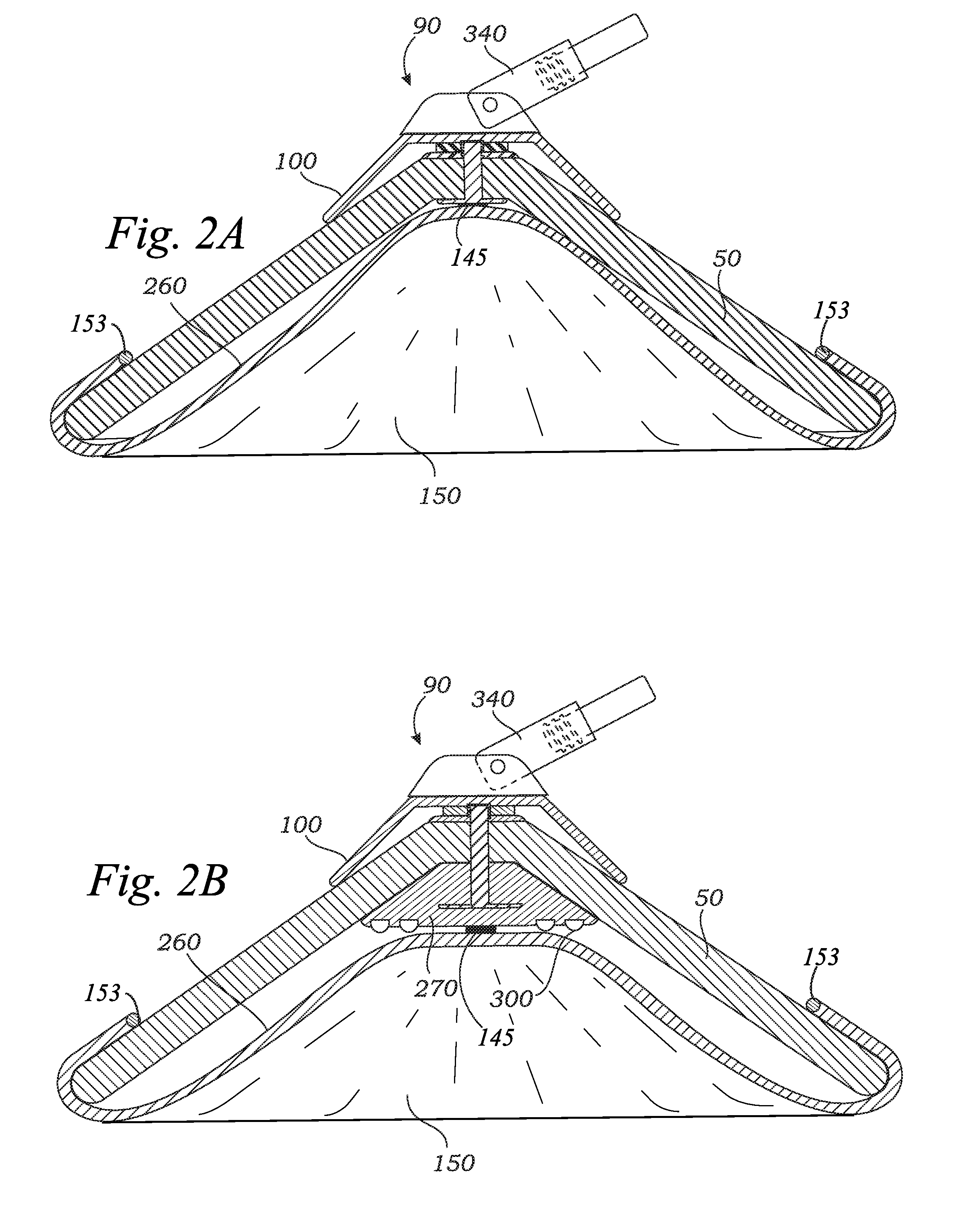
[0028]FIGS. 1 and 3 illustrate a scrubbing implement 10 for cleaning a surface 20. The scrubbing implement 10 includes a resilient base 30 that includes a plurality of resilient fingers 50, each of which are joined at a proximal end 60 to a hub 40 and extend radially away therefrom. Each finger 50 includes a distal end 70 opposite the proximal end 60. Preferably the hub 40 further includes a central aperture 80 therethrough. The resilient base 30 is preferably made from a resilient foam material such as EVA, or the like.

[0029]A rigid cap 90 comprises an inside upper end 120 and a wider open lower end 125. A frusta-conical side portion 100 is fixed at a top end 110 thereof to the upper end 120 of the cap 90. The upper end 120 preferably includes a central aperture 130 at least partially therethrough. The cap 90 preferably includes a handle receiving means 340 pivotally fixed to the cap 90 for receiving preferably a threaded end 350 of an elongated handle 360 (FIGS. 1 and 6), but may ...


PUM

PropertyMeasurementUnit
downward angleaaaaaaaaaa
flexibleaaaaaaaaaa
shapeaaaaaaaaaa

Abstract

A scrubbing implement for cleaning a surface with contours is disclosed. The scrubbing implement includes a resilient base that includes a plurality of resilient fingers, each of which extend radially away from center of the base. A rigid cap comprises an inside upper end and a wider open lower end. The cap preferably includes a handle receiving means pivotally fixed to the cap for receiving a threaded end of an elongated handle. A flexible pad is included that comprises a cleaning surface on a lower side thereof. The pad has a peripheral lip forming an aperture in the pad for receiving the distal ends of each finger of the base. In use, the base is fixed to the cap with the attachment means. The flexible pad is fixed around the distal ends of the fingers such that the pad may be applied to the surface to scrub the surface. The fingers and flexible pad conform to the shape of the surface. An additional resilient base is provided such that with the fingers pressed firmly against the surface each of a plurality of central scrubbing nibs contacts the back side of the pad to reinforce the pad against the surface, thereby providing additional scrubbing force to the surface. An alternate embodiment having a rotational scrubbing surface driven by a motor is also disclosed.

Description

CROSS-REFERENCE TO RELATED APPLICATIONS[0001]Not Applicable.STATEMENT REGARDING FEDERALLY SPONSORED RESEARCH AND DEVELOPMENT[0002]Not Applicable.FIELD OF THE INVENTION[0003]This invention relates to mops, and more particularly to a dual-mode contour-following mop.DISCUSSION OF RELATED ART[0004]Mops for cleaning cars are well known in the art. For example, the highly successful Shawala® multi-layer mop of U.S. Pat. No. 5,855,204, to Gray et al. on Jan. 5, 1999, teaches such a device. Such mops are made to conform to contours typical of motor vehicles, as a flat mop is essentially useless on such surfaces. The Gray device relies on the weight of water in a plurality of fingers to cause the fingers to follow contours on the surface. However, such weight is not always sufficient to create a strong enough cleaning force around such contours. Further, the central area of this device is too rigid and flat to adapt itself to contours.[0005]Mop devices that create a stronger cleaning force b...

Claims


Application Information

Patent Timeline
Patent Type & Authority Applications(United States)
IPC IPC(8): A47L13/12
CPCA46B11/0017A46B13/02A47L11/283A47L11/4036A47L13/24A47L13/12A47L13/20A47L13/22A47L11/4069
Inventor AIYAR, SANJAY
Owner AIYAR SANJAY
Why Eureka
Try Eureka