
Controlled translocation of a polymer in an electrolytic sensing system

a sensing system and polymer technology, applied in electrolysis, diaphragms, electrostatic separators, etc., can solve the problems of inability to achieve the advancement of both designs, inability to use dna hairpins as short strands, and inability to reduce current in direct proportion, so as to improve the spatial resolution of the channel blocking signal, reduce thermally induced motion of the polymer, and improve the effect of channel blocking signal

Active Publication Date: 2008-02-21
ELECTRONICS BIOSCI
View PDF9 Cites 65 Cited by
  • Summary
  • Abstract
  • Description
  • Claims
  • Application Information

AI Technical Summary

Benefits of technology

The present invention is about a system and method for measuring a signal that blocks a channel and controlling the movement of polymers like DNA through a fluid channel. The system includes two chambers with electrolytes and a barrier with a fluid channel in between. The barrier is attached to a cooling stage to reduce movement of the polymer due to temperature changes. A membrane with a protein pore can also be used to improve the signal and make the polymer less mobile.

Problems solved by technology

The technical problem addressed in this patent text is the need for a system and method to reduce the translocation velocity of a molecule through a detection channel and the diffusional motion of the molecule, while translocating, without limiting the molecule's length and without reducing the current blocking signal of interest.

Method used


Image

  • Controlled translocation of a polymer in an electrolytic sensing system
  • Controlled translocation of a polymer in an electrolytic sensing system
  • Controlled translocation of a polymer in an electrolytic sensing system

Examples


Embodiment Construction

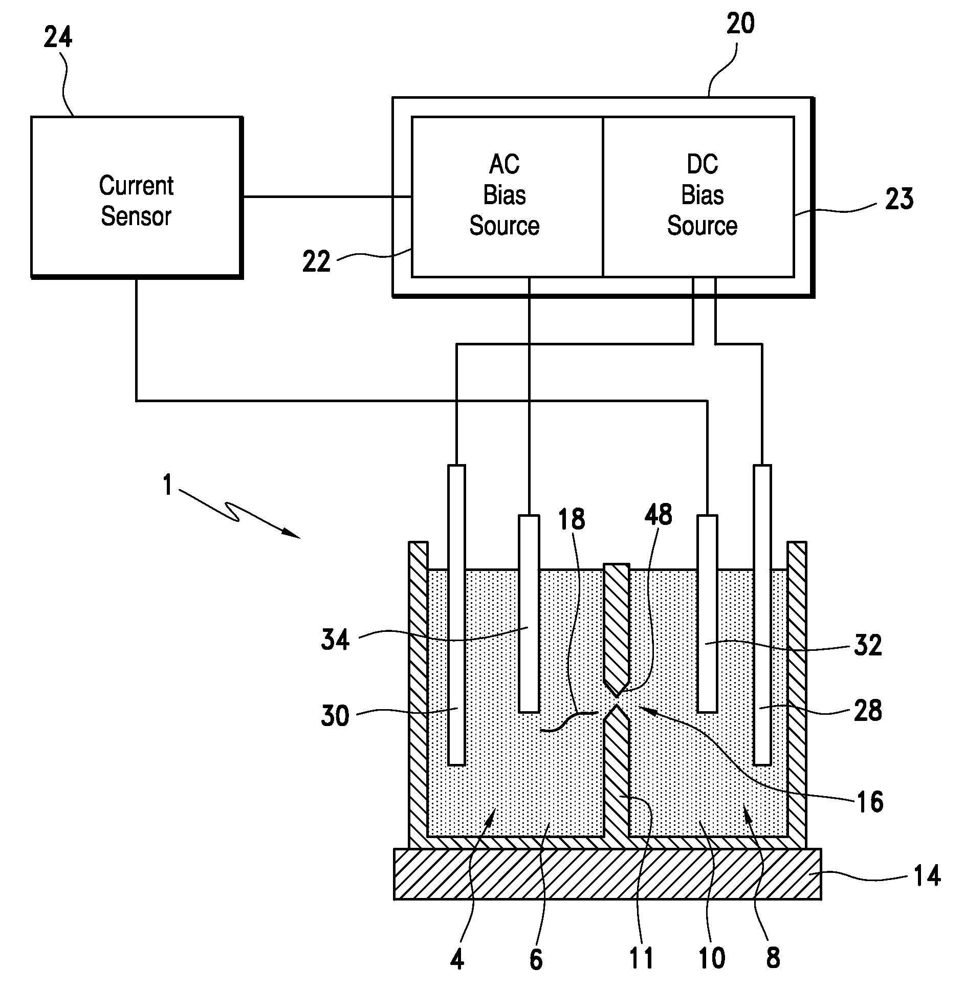
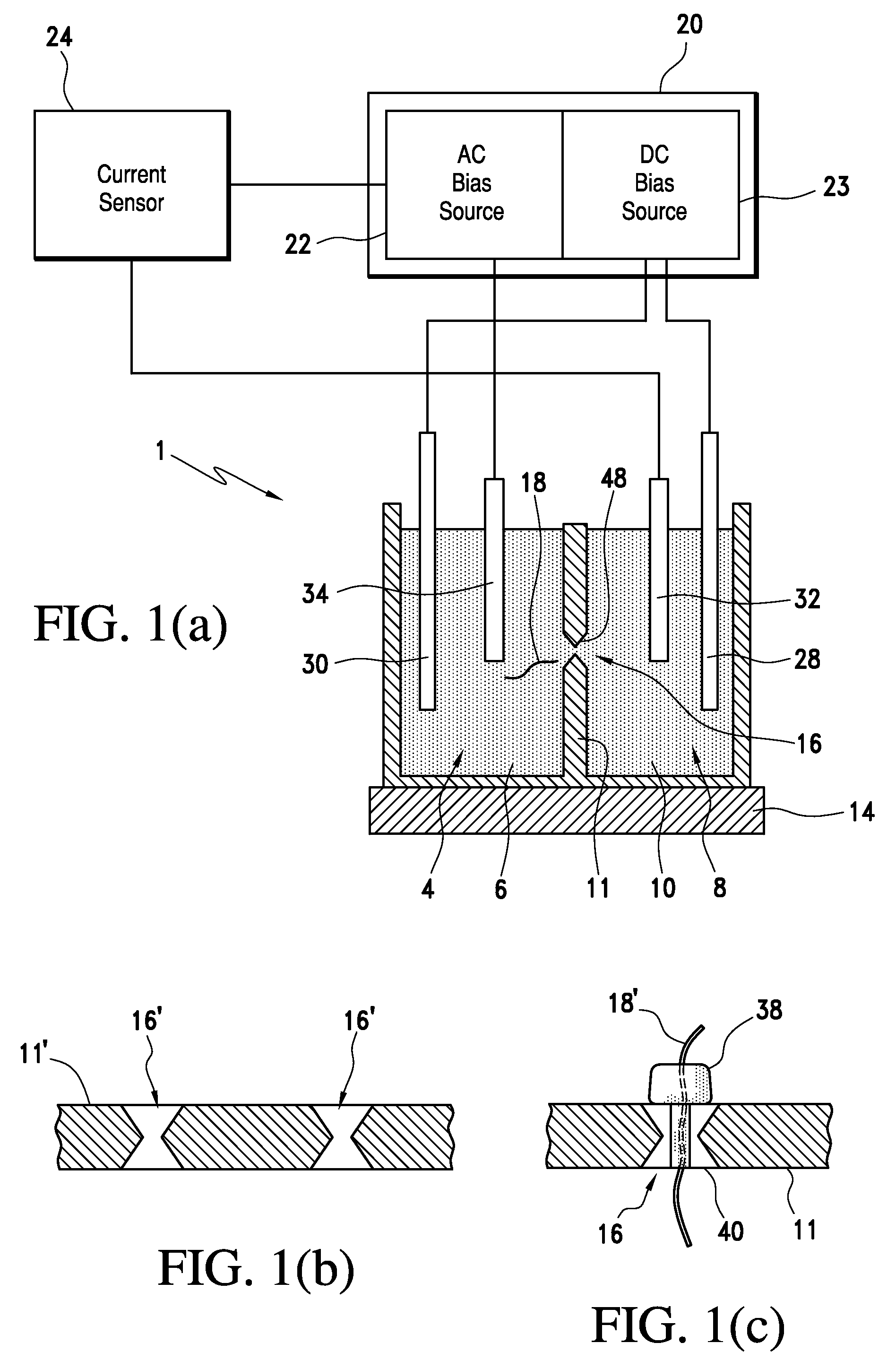
[0025]In general, the present invention is directed to a method and electrolytic sensing system for controlling the translocation of a molecule or polymer through a channel, in order to measure blocking signals corresponding to individual monomers. With initial reference to FIG. 1(a), sensing system 1 includes a first fluid chamber or electrolyte bath 4 within which is provided a first electrolyte 6, and a second fluid chamber or sensing volume 8 provided with a second electrolyte 10. Sensing volume 8 is separated from electrolyte bath 4 by a barrier structure 11, fluid path connecting first and second electrolytes 6 and 10. In an alternative embodiment depicted in FIG. 1(b), system 1 includes a barrier structure 11′ having multiple channels 16′ therein to provide for an array-type sensing system. Regardless, barrier structure 11 is joined to a substrate or stage 14. In a preferred embodiment, stage 14 is a temperature control stage. In general, system 1 controls the translocation o...


PUM

PropertyMeasurementUnit
Frequencyaaaaaaaaaa
Frequencyaaaaaaaaaa
Temperatureaaaaaaaaaa

Abstract

An electrolytic sensing system for measuring a blocking signal allows for controlled translocation of a molecule, such as DNA, through a fluid channel. A substantially constant electric field supplied by a DC source is applied across the fluid channel and induces translocation of the molecule within the system. An oscillating electric parameter (e.g. current or voltage) supplied by an AC source is also applied across the fluid channel as a means for measuring a blocking signal. The substantially constant electric field can be altered to provide more detailed control of the molecule and, optionally, run a select portion of the molecule through the channel multiple times to provide numerous signal readings. A temperature control stage cools the system, providing further control of molecule translocation. A modified or non-modified protein pore may be utilized in the fluid channel. The system allows for long DNA strands to be sequenced quickly without amplification.

Description


Claims


Application Information

Patent Timeline
Owner ELECTRONICS BIOSCI
Learn More