Driving method for el displays with improved uniformity

a technology of electroluminescent flatpanel display and driving method, which is applied in the direction of static indicating devices, instruments, etc., can solve the problems of reducing the dynamic range and image artifacts, affecting the uniformity of the display, and the circuit is typically much larger and more complex, so as to reduce the differential aging of the el materials and the tfts in the display.

a technology of electroluminescent flatpanel display and driving method, which is applied in the direction of static indicating devices, instruments, etc., can solve the problems of reducing the dynamic range and image artifacts, affecting the uniformity of the display, and the circuit is typically much larger and more complex, so as to reduce the differential aging of the el materials and the tfts in the display.

US20080042938A1Inactive Publication Date: 2008-02-21EASTMAN KODAK CO

Image

  • Driving method for el displays with improved uniformity
  • Driving method for el displays with improved uniformity
  • Driving method for el displays with improved uniformity

Examples


Embodiment Construction

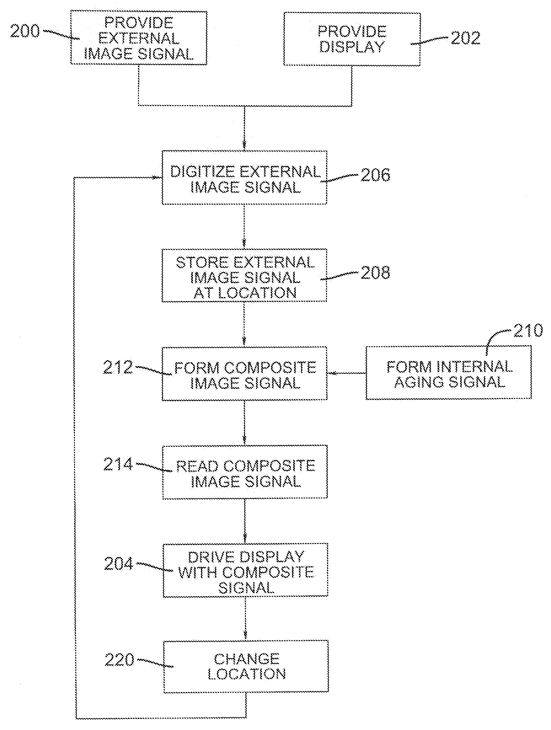
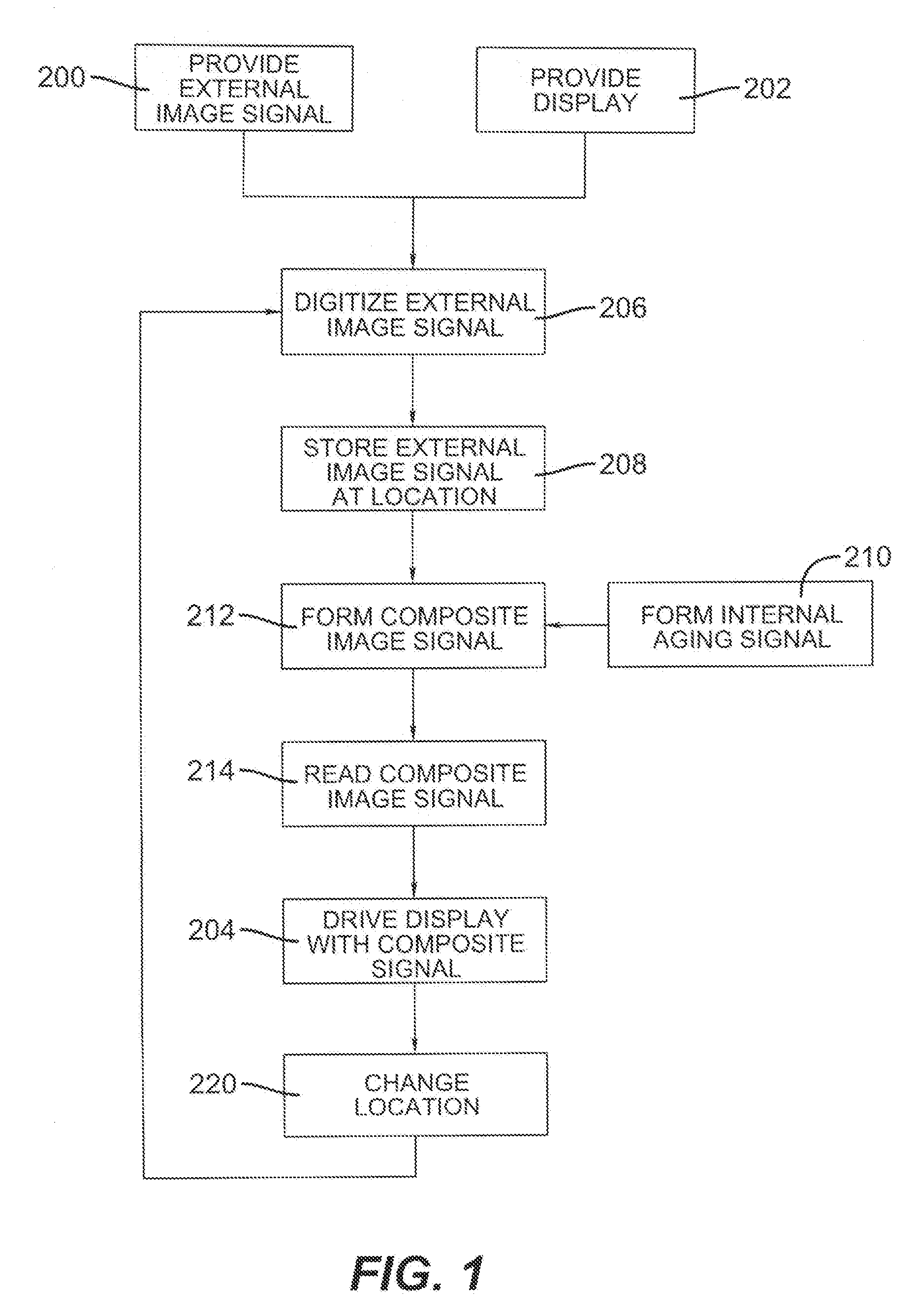
[0031]Referring to FIG. 1, a method of driving an EL display having a plurality of light-emitting display elements having outputs that change with time or use, comprises the steps of providing 200 an external image signal with a first image aspect ratio; providing 202 an EL display having light-emitting display elements formed in a two-dimensional array having a second display aspect ratio different from the first image aspect ratio; driving 204 all of the two-dimensional array of display elements with a composite signal comprising the external image signal and an internal aging signal, wherein a subset of the display elements is driven by the external image signal and the remainder of the display elements that are not driven by the external image signal are driven with the internal aging signal; and changing 220 the location of the subset of display elements within the two-dimensional array driven by the external image signal over time. The composite signal may be formed 212 in a v...


PUM


Abstract

A method of driving an electroluminescent (EL) display having a plurality of light-emitting display elements having outputs that change with time or use, comprising the steps of: a) providing an external image signal with a first image aspect ratio; b) providing an EL display having light-emitting display elements formed in a two-dimensional array having a second display aspect ratio different from the first image aspect ratio; c) driving all of the two-dimensional array of display elements with a composite signal comprising the external image signal and an internal aging signal, wherein a subset of the display elements is driven by the external image signal and the remainder of the display elements that are not driven by the external image signal are driven with the internal aging signal; and d) changing the location of the subset of display elements within the two-dimensional array driven by the external image signal over time.

Description

CROSS-REFERENCE TO RELATED APPLICATIONS[0001]This is a continuation-in-part of application Ser. No. 11 / 464,688, filed Aug. 15, 2006 entitled “Driving OLED Display With Improved Uniformity” by Ronald S. Cok.FIELD OF THE INVENTION[0002]The present invention relates to solid-state electroluminescent flat-panel display devices and more particularly to methods for driving such display devices to reduce differential aging of the light-emitting display and provide improved display uniformity.BACKGROUND OF THE INVENTION[0003]Electroluminescent (EL) devices are a promising technology for flat-panel displays and area illumination lamps. For example, Organic Light Emitting Diodes (OLEDs) have been known for some years and have been recently used in commercial display devices. EL devices rely upon thin-film layers of materials coated upon a substrate, and include organic, inorganic and hybrid inorganic-organic light-emitting diodes (LEDs). The thin-film layers of materials can include, for exam...

Claims


Application Information

Patent Timeline
21 Feb 2008
Publication
US20080042938A1
IPC
G09G3/30
CPC
G09G3/007; G09G3/3216; G09G3/3225; G09G2340/0442; G09G2320/029; G09G2320/043; G09G2310/0232
Inventors
COK, RONALD S.