Tolerance ring having variable height and/or assymmetrically located bumps

a technology of tolerance rings and bumps, applied in the field of tolerance rings, can solve problems such as data loss, tribological failure of interfaces, and damage to disks and heads, and achieve the effect of reducing torque rippl

a technology of tolerance rings and bumps, applied in the field of tolerance rings, can solve problems such as data loss, tribological failure of interfaces, and damage to disks and heads, and achieve the effect of reducing torque rippl

US20080043375A1Active Publication Date: 2008-02-21INTRL PLEX TECH INC

Image

  • Tolerance ring having variable height and/or assymmetrically located bumps
  • Tolerance ring having variable height and/or assymmetrically located bumps
  • Tolerance ring having variable height and/or assymmetrically located bumps

Examples


Embodiment Construction

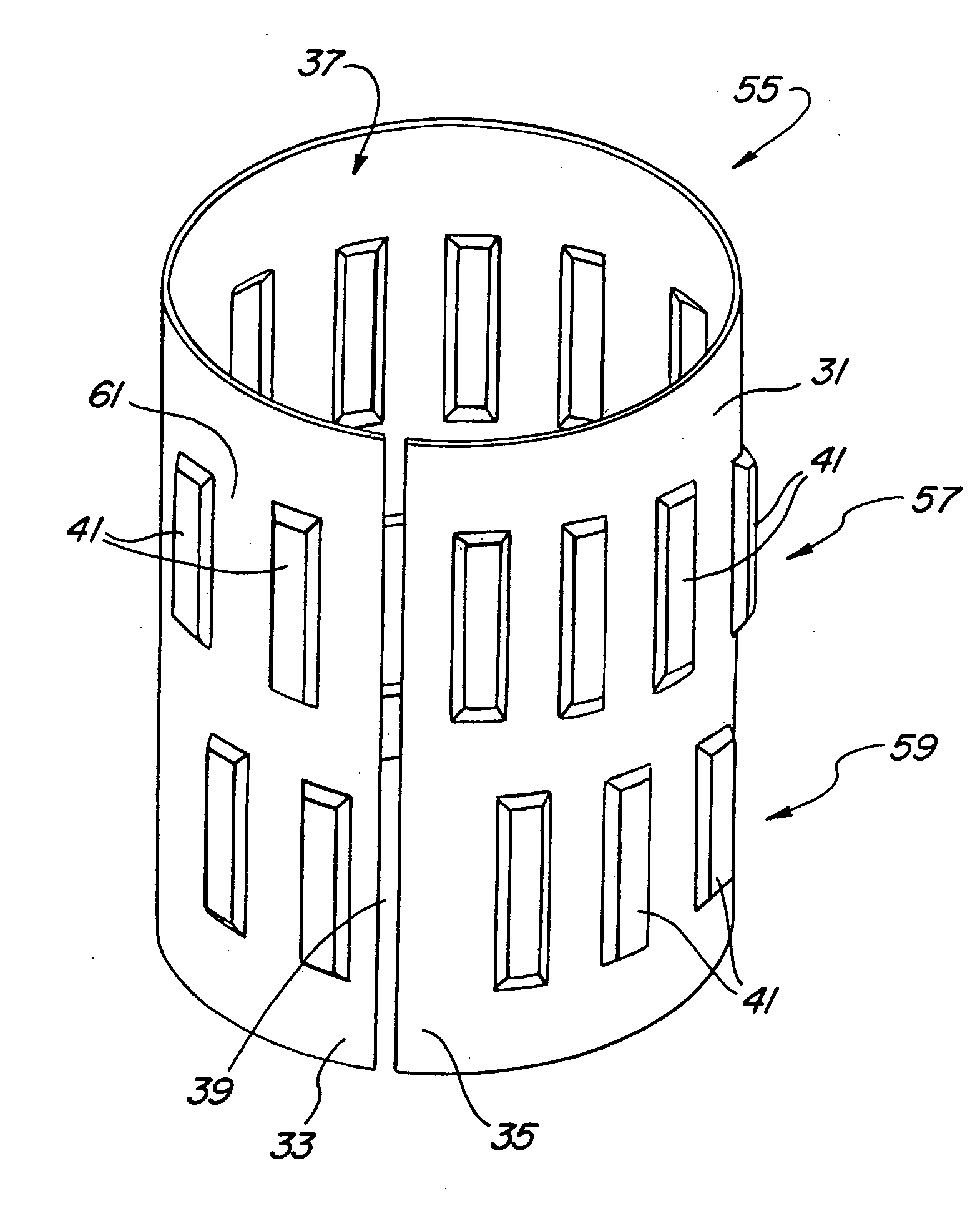
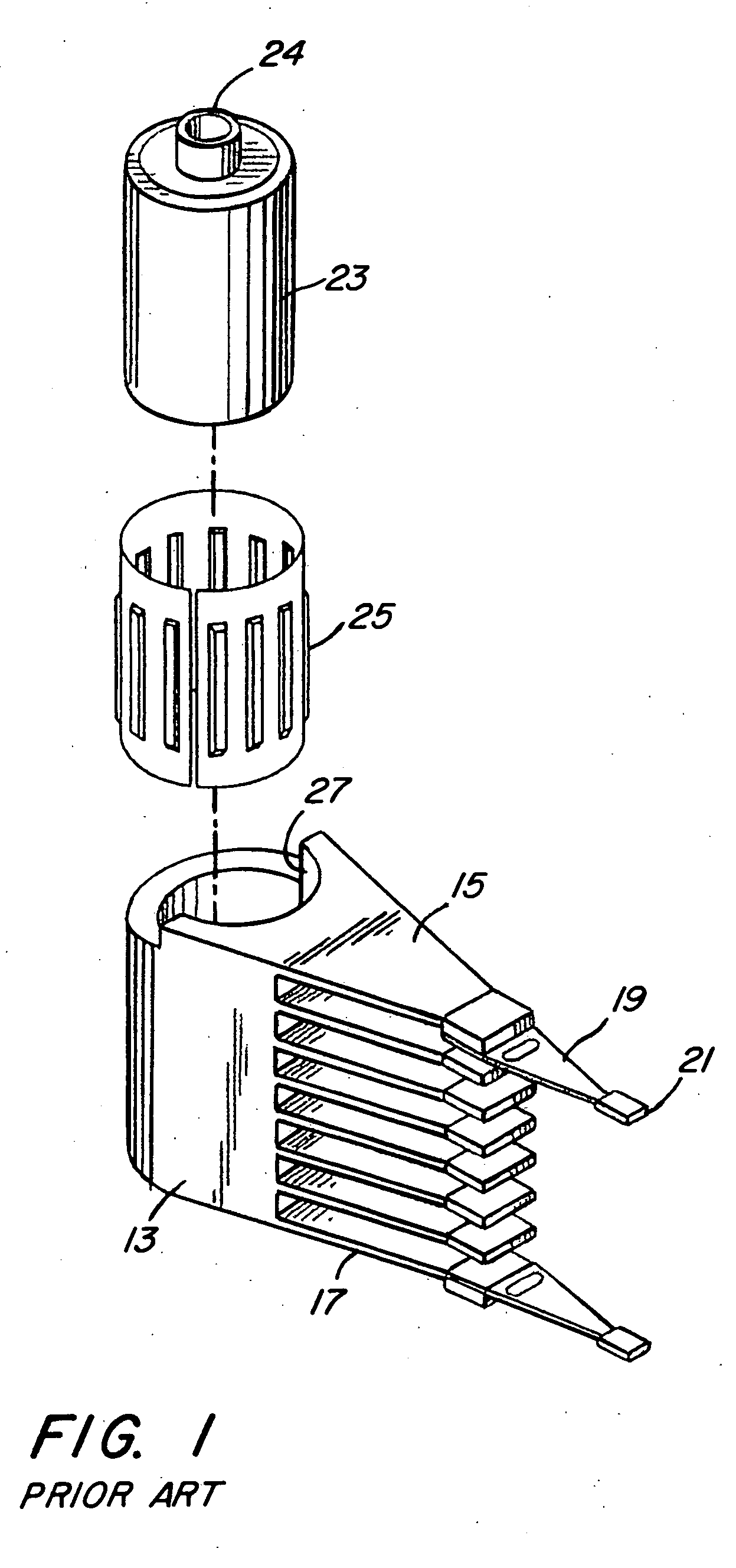
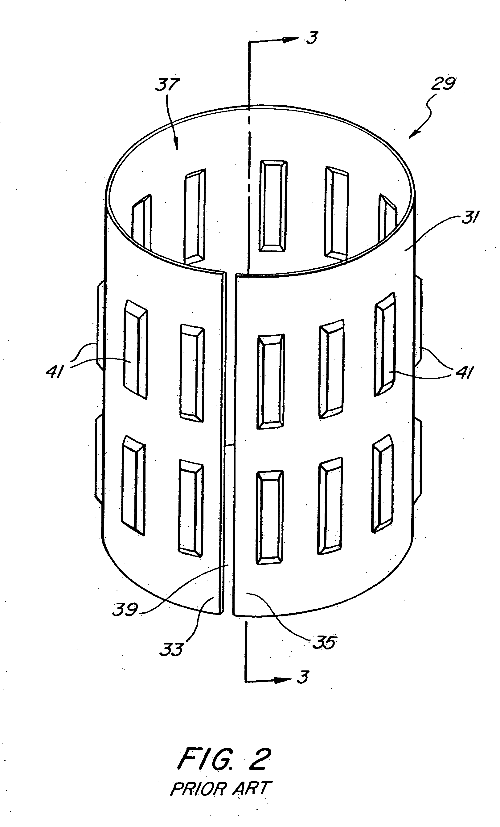
[0032]FIG. 1 is an exploded view of an-actuator arm assembly 13 which includes a pivot bearing cartridge 23. The pivot bearing cartridge 23 is cylindrical in shape and includes a shaft 24 about which the actuator arm assembly 13 rotates. The actuator arm assembly 13 has an opening or bore 27 therein. The pivot bearing cartridge 23 fits within the bore 27 of actuator arm assembly 13. The tolerance ring 25 fits within the space between the bore 27 and the outside diameter of the pivot bearing cartridge 23.

[0033]Actuator arm assembly 13 has a plurality of arms 15 in the head-stack assembly 17. Each arm 15 typically carries at least one suspension 19. Attached to the suspension 19 are recording heads (sliders) 21 which include magnetic transducers that magnetize the surface of the disc (not shown) to represent and store the desired data.

[0034]The tolerance ring 25 can be installed first into the bore 27 of actuator arm assembly 13 so that later a generally cylindrical inner part, such a...


PUM

PropertyMeasurementUnit
widthaaaaaaaaaa
widthaaaaaaaaaa
distanceaaaaaaaaaa

Abstract

A tolerance ring configured to reduce torque ripple for a pivot bearing in an actuator arm assembly. The tolerance ring comprises a cylinder having a predetermined length, and a first and a second row of contacting portions arranged around the surface of the cylinder, the contacting portions of the second row are circumferentially displaced with respect to the first row by a distance greater than zero but less than the distance of the contacting portion and the spacing between adjacent contacting portions in the first row.

Description

BACKGROUND OF THE INVENTION[0001]1. Field of the Invention[0002]This invention relates generally to bearing tolerance rings. More particularly, the invention pertains to tolerance rings used in cartridge bearings for actuator arms in information storage devices, such as hard disk drives.[0003]2. Description of Related Art[0004]A key component of any computer system is a device to store data. One common place for storing massive amounts of data in a computer system is on a disc drive. The most basic parts of a disc drive are a disc that is rotated, an actuator that moves a transducer to various locations on the disc, and electrical circuitry that is used to write and read data to and from the disc. Coupled to the actuator is a head-gimbal assembly (HGA) that includes a head and metal suspension. The HGA's can be stacked together into a head-stack assembly (HSA), which is propelled across the disk surface by the actuator. There are a variety of disc drives in use today, such as hard d...

Claims


Application Information

Patent Timeline
21 Feb 2008
Publication
US20080043375A1
IPC
G11B5/55
CPC
F16C27/00; F16D1/0835; F16C11/04; G11B25/043; F16C41/008; G11B5/4813; F16C2370/12
Inventors
HANRAHAN, KEVIN P.; SCHMIDT, RYAN J.